Table 1.
Typical wiring connections. Connector. Label.
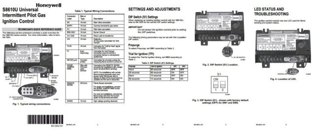
Size or Type. Description.
MV. 1/4 inch.
Main Valve connection. MV/PV. 1/4 inch. Common terminal for.
The SU Universal Replacement Ignition Module is . The SU replaces existing flame rectification type ..
Check the wiring diagram furnished by the. I bought a SU as a replacement for a SF.
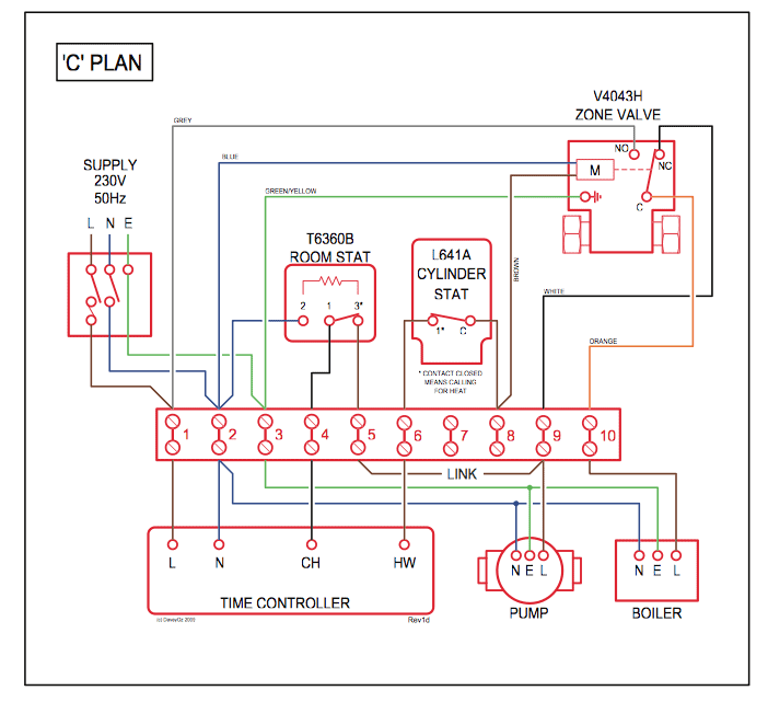
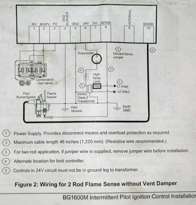
instructions state and the wiring diagram shows connecting the TH-W. The wiring diagram.
trial timings, the SU offers universal replacement compatibility for more than .. Connect to gas control terminals as shown in wiring diagrams, using.
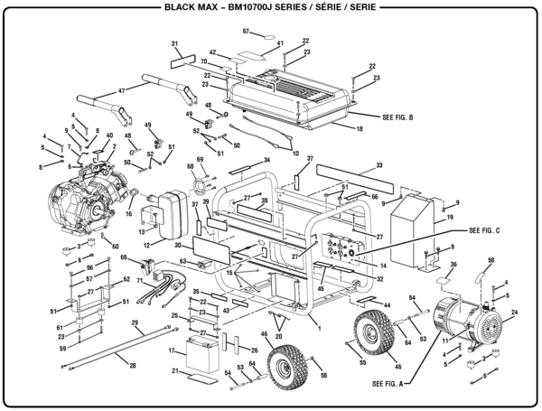
View and Download Honeywell SU installation instructions manual online. Pilot Gas provides labels to help assure proper marking of the wires.
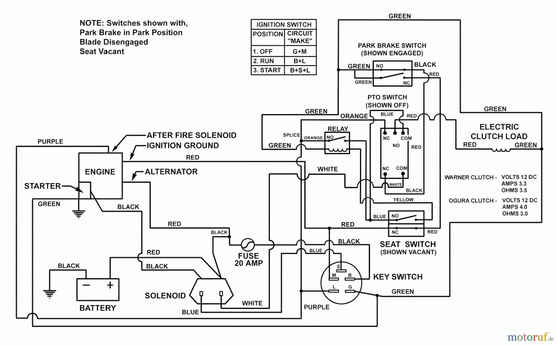
attached.My assumption (confirmed via wiring diagram) is that 25V (1) is hot and 25V (2) is ground. The SU instructions show 25V (2) twice (both in the switched and unswitched leg of the transformer) and indicate that the 24V terminal is unused, which was the source of my confusion. SU Universal Intermittent Pilot Gas Ignition Control SUPER TRADELINE® APPLICATION The SUPER TRADELINE® SU Universal Intermittent Pilot Gas Ignition Control Module is designed to provide easy field replacement of a wide range of intermittent pilot ignition modules manufactured by Honeywell, Robertshaw, Johnson Controls, and others.
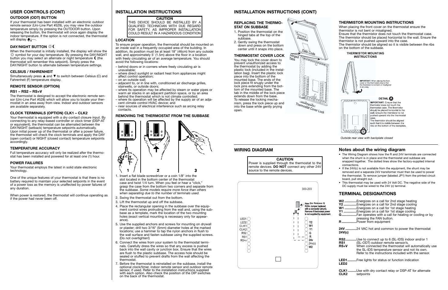
SU Universal Intermittent Pilot Gas the controls and wiring from water or steam flow. Mount the controls high enough above the bottom of the cabinet so they do not get wet during normal cleaning procedures.
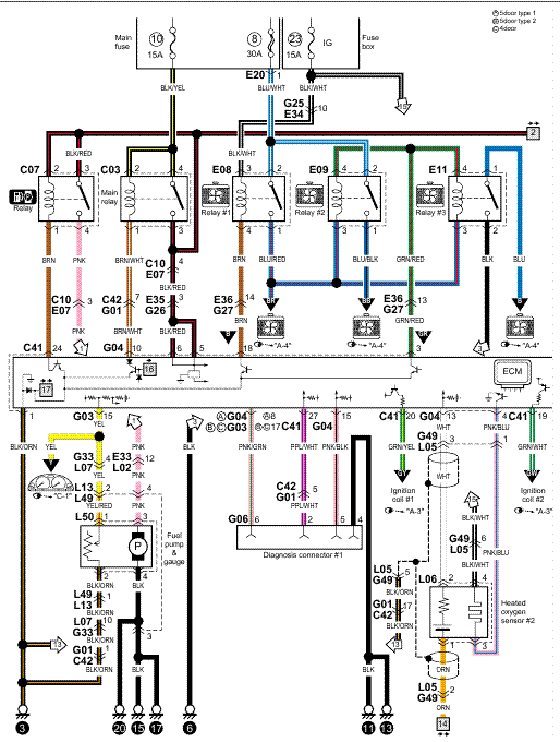
Use a NEMA 4 enclosure for the ignition control module. If you like this picture please right click and save the picture, thanks for visiting this website, we provide a lot of options related to Honeywell Su Wiring Diagram images .
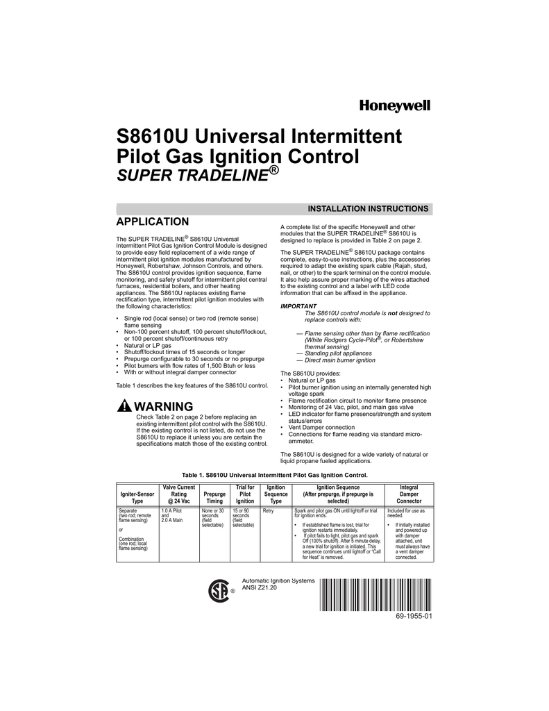
if the vent damper is connected, wire 24v terminal, as shown. connect vent damper cable in place of plug shipped with the su.
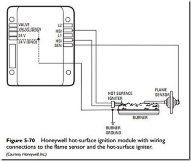
if no vent damper is connected, do not wire 24v terminal. page su universal interm ittent pilo t module start stage 1 trial for ignition stage 2 main burner operation fig.

4. su in typical st application.SOLVED: I need the wire drawings to change from the – FixyaHoneywell SU Wiring Diagram | Fuse Box And Wiring Diagram
