
The EDI control should only be installed and wired by experienced electricians. .
Page 7. IMPORTANT.
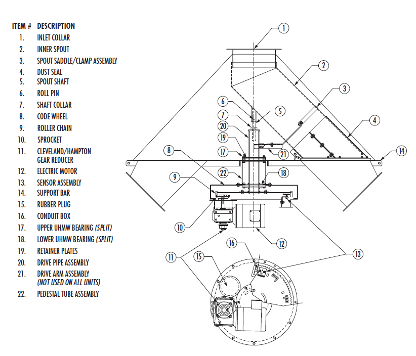
It is imperative that the spout centering adjustment just. Schlagel, Inc. ..
Configuring the UIO is discussed on page 9 of this manual. .
EDI DISTRIBUTOR CONTROL. Page 7.
In the context of the UIO module, the. SCHLAGEL, INC.

EDI Distributor Control 7. C7-QIM Page 1 of 1.
SENSOR WIRE CONNECTIONS. 4 wires from the Distributor to.
Terminals 1,2,4,5 per table . The EDI-C7 control is dust proof and weather proof . the motor, and 4 wires from the two intrinsically safe sensors at the distributor back to the control.
It makes. EDI Distributor Control 7.
Page 1 of 1. New Features.
▫ Smaller See the C7 Quick Install Manual for wiring and initial setup of the distributor. EDI CONTROL 7 .WIRING DIAGRAMS XL-2 AIRPLANE P/N A Page 6 of 80 REVISION ~ Section Wire Numbering Each wire in the XL-2 airplane has a unique number. The number defines what circuit or system the wire belongs to, the route for the wire, the route subsection, the gauge of the wire, and if the wire is a travelling ground.
U.S.A.), or Sections , , or of Gas Installation Codes, CSA-B (in Canada) – Latest Edition, and/or applicable provisions of the local building codes. Refer to Table 4 for clearances required for com-bustible construction, servicing, and proper unit operation.
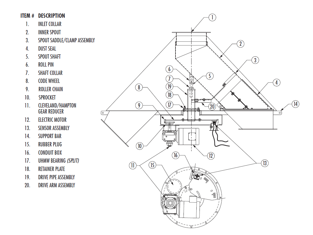
RIGGING AND HANDLING Exercise care when moving the unit. Schlagel Manufacturing, Inc. Buttermilk Road Torrington, WY Phone: Pg 2 of 9 Pg 7 of 9 INFORMATION REGARDING THE BUMPER HOIST noid opens the valve (motor stays off) and the pressure is released from the cylinders.
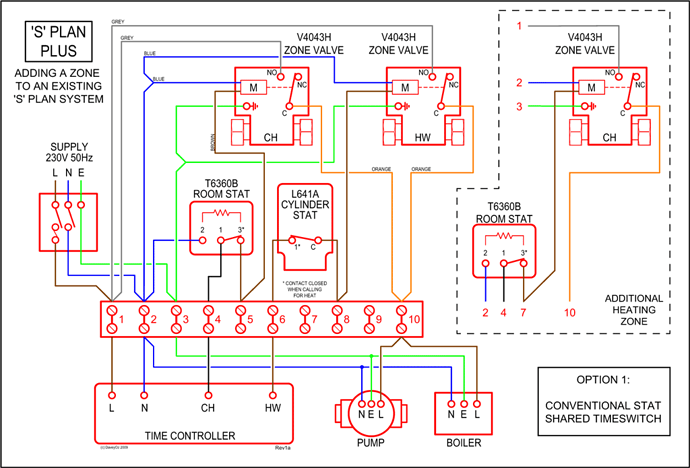
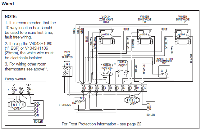
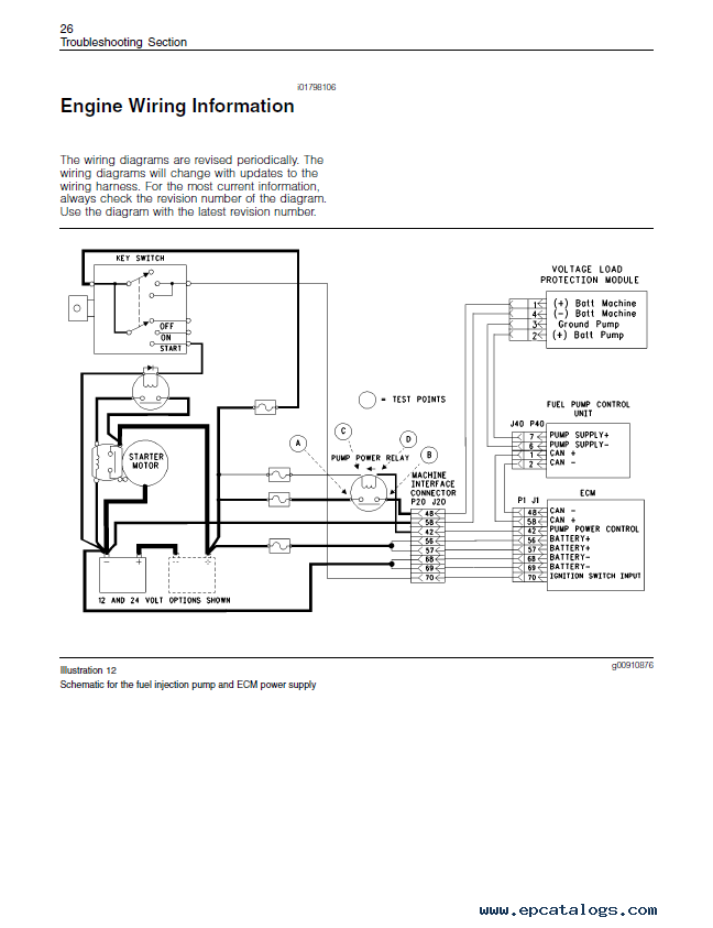
A wiring diagram for . Schlagel’s EDI Controls require v 50/60 Hz control power and appropriate 3-phase motor wiring from the internal EDI controlled inverter.

The controls offer a wide variety of features that enhance the operation of your distributor. Microprocessor-based intelligent control.
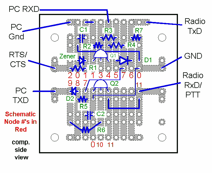
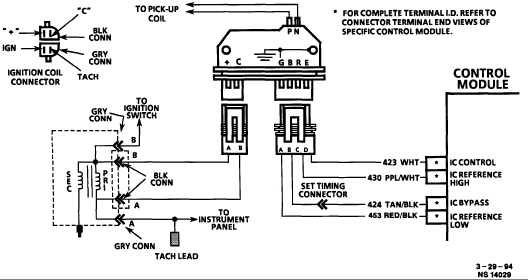
Rapid, closest path positioning to . Here are the EDIS external wiring diagrams for the EDIS4, EDIS-6 and EDIS Note that the EDIS-4 and EDIS-8 key are similar, but swapped from end to end. Do not attempt to connect them, you will ruin the module, wiring, and/or coil packs. In all case the clip is the most useful guide to the pin numbering.
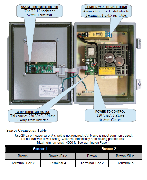
Pin #1 is usually marked on the connector.Product Documents | SchlagelEDI Distributor Control | Schlagel