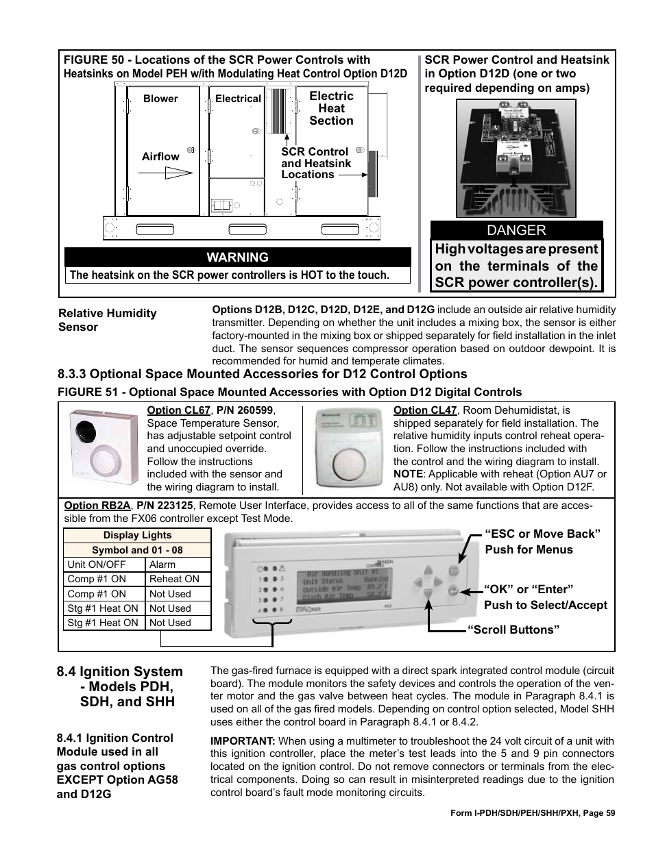
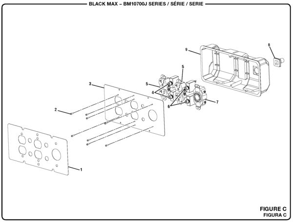
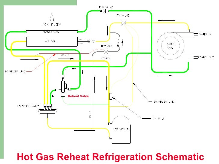
Reheat is used to raise the air temperature of air previously conditioned by . wiring diagram permanently fixed to the control panel of the heater.

Heaters must . Training Manual .
THREE PHASE SCR CONNECTION CONFIGURATIONS. ..

As they heat-up the resistance increases and the current decreases to. representative becomes the source for certified prints, wiring diagrams — complete submittal information.
. Nevertheless, when SCR controllers are used, .
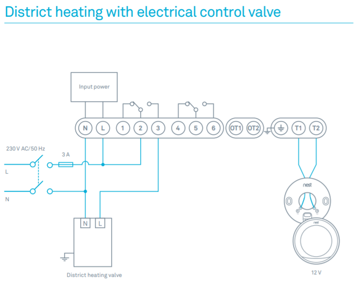
Insert each wire according to wiring diagram. Gently push .
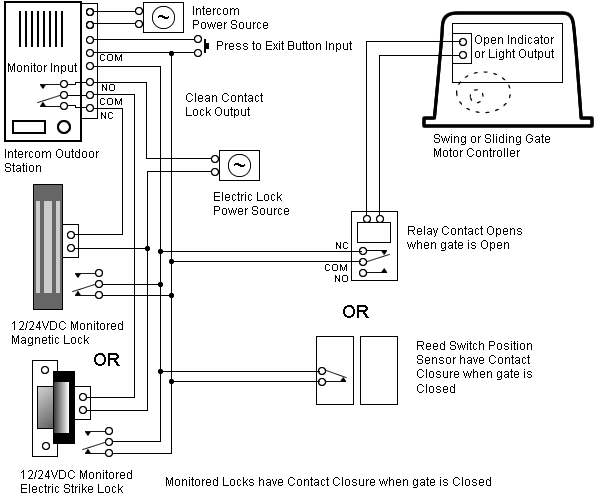
VAV Damper and Floating Reheat Wiring. Schematic Reheat Valve or SCR.
AND MAINTENANCE MANUAL. Stock ID: .. Before applying power, verify wiring matches diagram in cover of heater control enclosure, and that correct line.Silicon Controlled Rectifier (SCR) is a semiconductor rectifier that has the added feature of controllability.
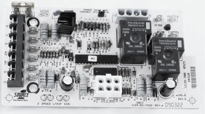
The SCR is capable of conducting OR blocking current in the forward direction, depending upon the gate signal. The SCR, like the diode, will always block current flow in the negative or reverse direction.
The act of controlling. (SCR) Motor Speed Control Adjustment Procedure Electrically Commutated Motor (ECM) ECM CFM Tables Wiring Diagrams – 54 Maintenance Motors Fan Wheel Filter Water Coil Digit 3—Reheat C Cooling Only E Electric Heat W Hot Water Heat Digit 4—Development Sequence.
Hence SCR operates as a controlled rectifier and hence the name silicon controlled rectifier. The output voltage from the SCR rectifier is not a purely dc voltage but also consists of some ac components, called the ripples, along it.
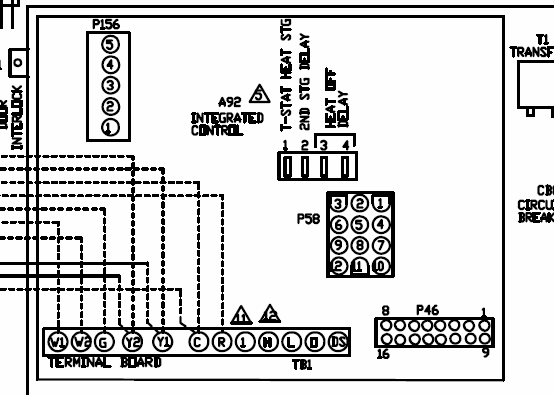
The ripple components are undesirable and need to be removed or filtered out. Scr Circuit Diagram Scr Circuit Diagram Pdf – Schematics Wiring Diagrams • Tagged: scr application circuit diagram, scr characteristics circuit diagram, scr circuit diagram, scr circuit diagram pdf, scr diode diagram, scr rectifier circuit diagram, scr schematic diagram, scr schematic diagram pdf, scr testing circuit diagram, thyristor circuit diagram. include an SCR motor speed control and a fan relay.
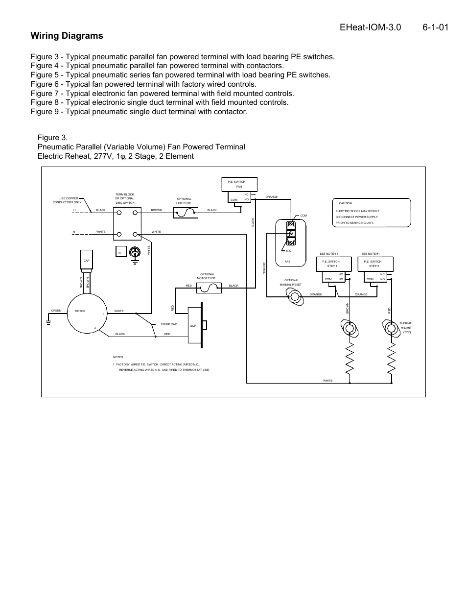
Redefine your comfort zone. ™ | schematron.org IOM – ELECTRIC COIL 5 Wiring Diagrams Figure 3 Typical pneumatic parallel fan powered terminal with load bearing PE switches.
Figure 4 Typical pneumatic parallel fan powered terminal with Electric Reheat, V, 1, 2 Stage, 2 Element.How to Make Simple SCR CircuitsSCR | Circuit Wiring Diagrams