
Securitron Magnalock Corp. IDEAL SOLUTION = Manual Reset Option BPS VAC.
24VDC. 2 AMP.
%. %.
4. W/PSM W/FAR BPS FAR – Fire Alarm Reset by Securitron. Manual Door Lock Power Reset for Code Compliance! The FAR module provides functionality (beyond a standard fire.
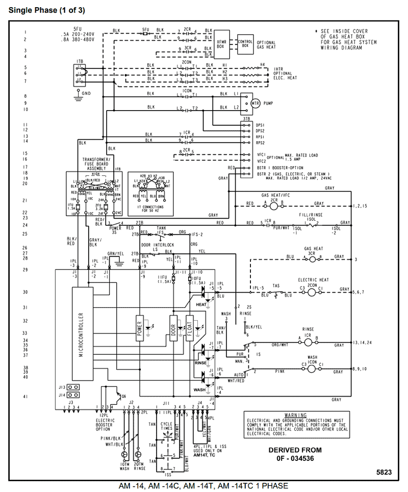
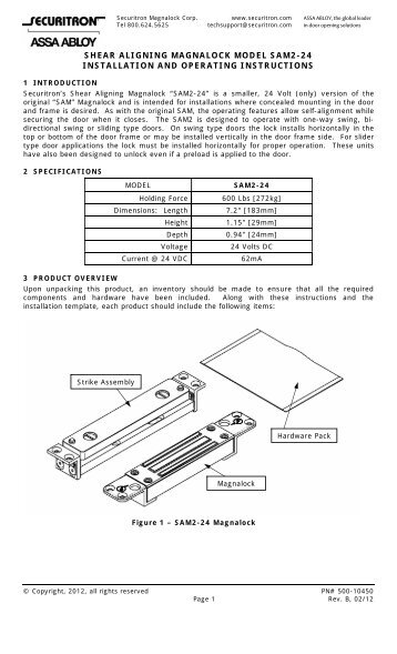
Securitron’s Shear Aligning Magnalock “SAM” is a smaller, 24 Volt (only) .. If the strike is not pulled up to the face of the Magnalock, the strike is to far away from The following diagram, Figure 13, represents the proper electrical wiring.
Securitron® BPS 12/ Dual-Voltage Linear Power Supply | How to Order. Dimensions.
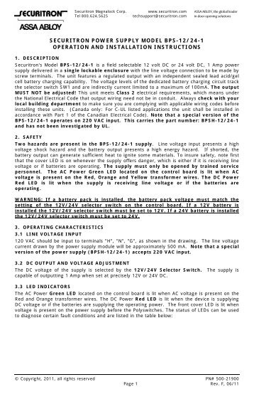
Model . Outputs. AC Loss and Low.
Battery Status. Manual.
Reset Option. BPS/ VAC.
12/24 VDC. 1A.
Y W/FAR BPS VAC. Need installation instructions for any ASSA ABLOY product?
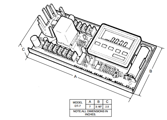
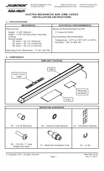
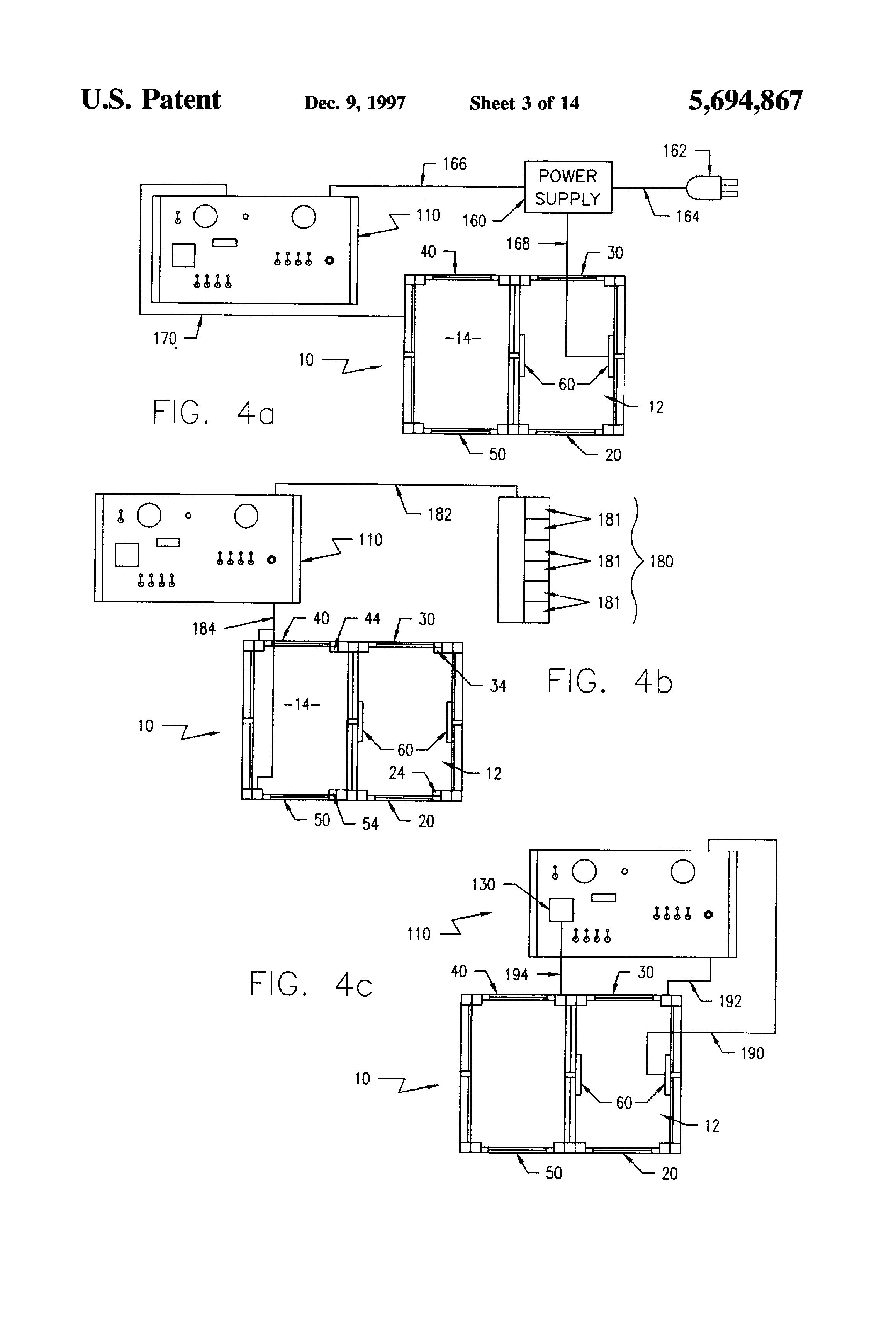
Check our installation DPA, DPA Installation and Operating Instructions · DT-7 Installation.Electromagnetic Door Holder/Releases Door Control for Fire and Smoke Barrier Doors and Other Remote Refer to Diagram B • How far is the centerline of the pivot/hinge from the wall? “A” dimension • Concealed Wiring • AnSi/C Product Description & Features • total Projection: /4″ (95mm).
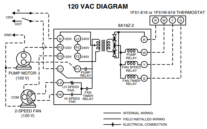
SECURITRON EEB2, EEB3N EXIT BUTTON WITH INTEGRATED TIMER INSTALLATION AND OPERATING INSTRUCTIONS 1. DESCRIPTION identification of the wires and a typical wiring diagram showing a power supply, motion detector, customer within 24 hours of SECURITRON’s receipt of the product from customer.

If the customer has an. Securitron AQDR Data Sheet.
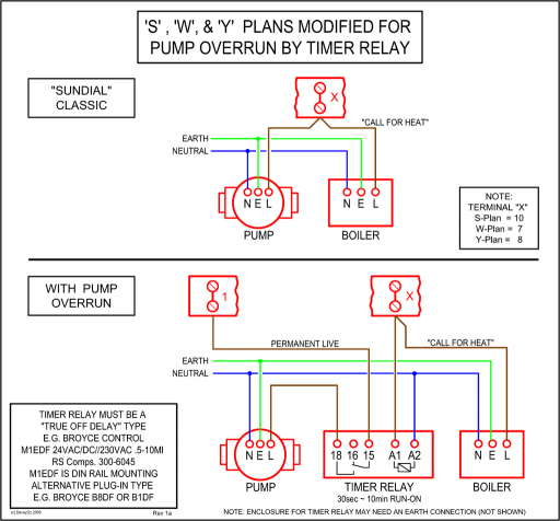
make sure power supply. time period reset units and external alarm devices have been connected correctly according to wiring diagram shows “text 1” after a short intro procedure. +30() Documents Similar To MartechnicLtd BNWAS U-WAS UserManual (1) KENR Uploaded by.
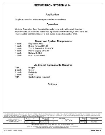
speedyben. No, usually you will need to provide separate power for the keypad system. If the strike has a large enough in-rush current to max out the transformer, the keypad system will crash.
An inexpensive plug-in D/C power supply would suffice, such as Securitron part # PSP or PSP The FAR module is designed to work in conjunction with the Securitron BPS and BPSM series power supplies and a fire alarm panel (by others). Whenever the FAR receives a signal from the fire alarm it will switch off the output of the BPS/BPSM power supply.Securitron – Fire Alert Reset Control 24vdc – FAR – schematron.org# New Bright Rc Car Batteries 12 8 #
