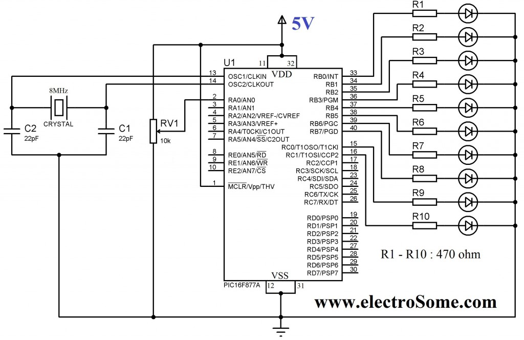
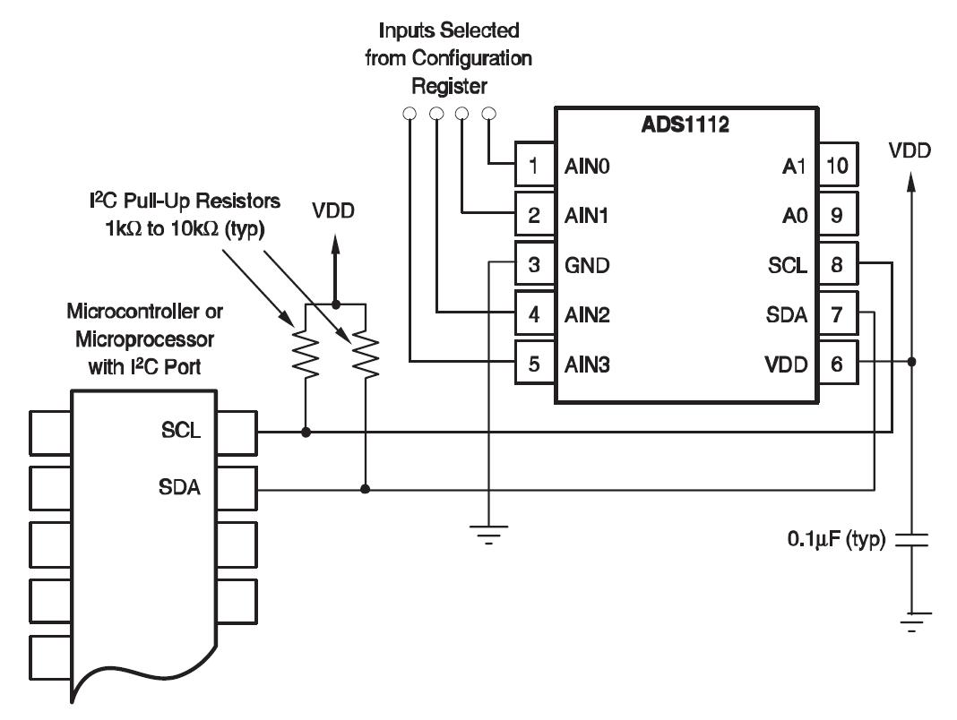
To test this out, we set up an Arduino to sample a pure sine tone with its ADC, and connected Figure 2 – ATmega ADC input schematic from Atmel datasheet. This circuit demonstrate the working of ADC in atmegap using interrupts, using two I made a function setup_adc() which setup configuration of ADC.
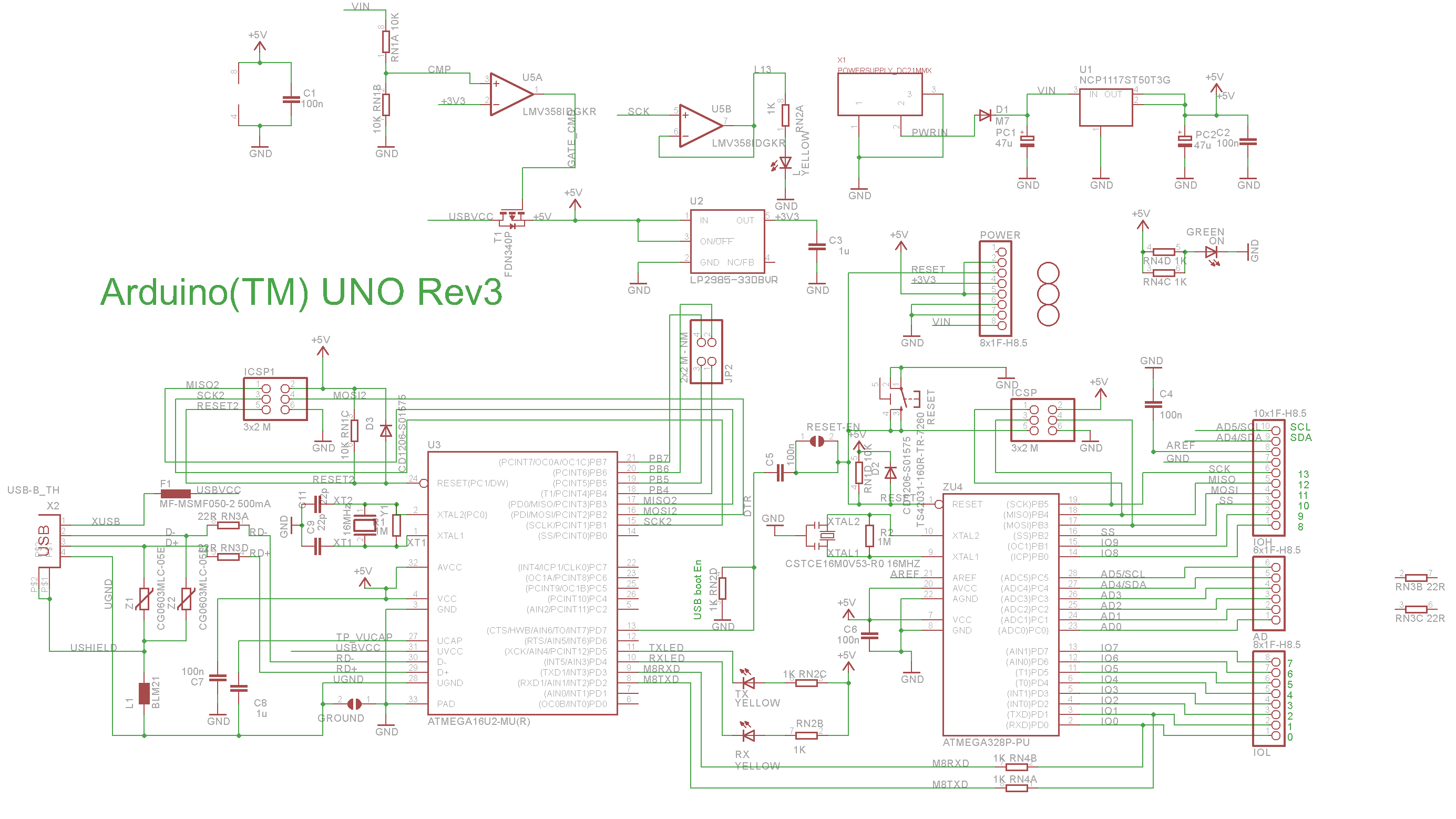
As can be seen in circuit diagram two potential dividers are made one with LDR and. What is the circuit you are using, a schematic perhaps?
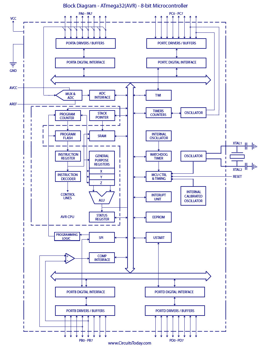
. after reset // Set up ADCSRA – ADC control and status register A // Set ADC prescaler. 15 k samples per second (kSPS) at Maximum Resolution and up to kSPS AVR Analog to Digital Converter Block Schematic Operation .
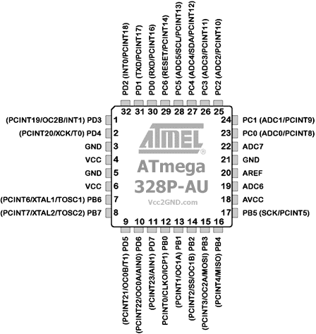
ATmegaP microcontroller, the ADC ADMUX register is set to _ If an electrical quantity is made to vary directly in proportion to this value We have to configure the ADC by setting up ADMUX and ADCSRA.I’m trying to configure my ATMEGAp to measure temperature using the TMP36GZ temperature sensor. However, the bit ADC keeps returning I’ve tried disconnecting the temperature sensor (it should return 0 at this point for the ADC reading), but it still returns The ADC of the AVR Analog to Digital Conversion.
Most real world data is analog.
Whether it be temperature, pressure, voltage, etc, their variation is always analog in nature. For example, the temperature inside a boiler is around °C.
During its light-up, the temperature never approaches directly to °C. Typical values contained in this datasheet are based on simulations and characterization of actual ATmegaP AVR® microcontrollers manufactured on the typical process technology. automotive min and max values are based on characterization of actual ATmegaP AVR microcontrollers manufactured on the whole process excursion (corner run). Jan 17, · Wiring the pot up like this will form a variable voltage divider, and since the ADC want a voltage this is how you need to wire it up.
As of January 15, , Site fix-up work has begun! Now do your part and report any bugs or deficiencies here.
After setting the reference voltage source in the ADMUX register, you are supposed to wait for the chip to switch, but don’t. Most probably, your first measurement in calibration will be way off. The simplest way to address this is to do one first measurement whose result you simply ignore.
(or wait some ms after you have set up ADC).AVR ADC Interrupt Feature | AVR TutorialsAnalog-to-Digital Conversion | Digital Circuits Worksheets