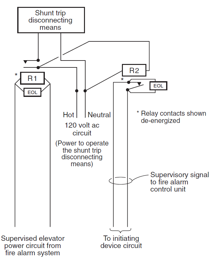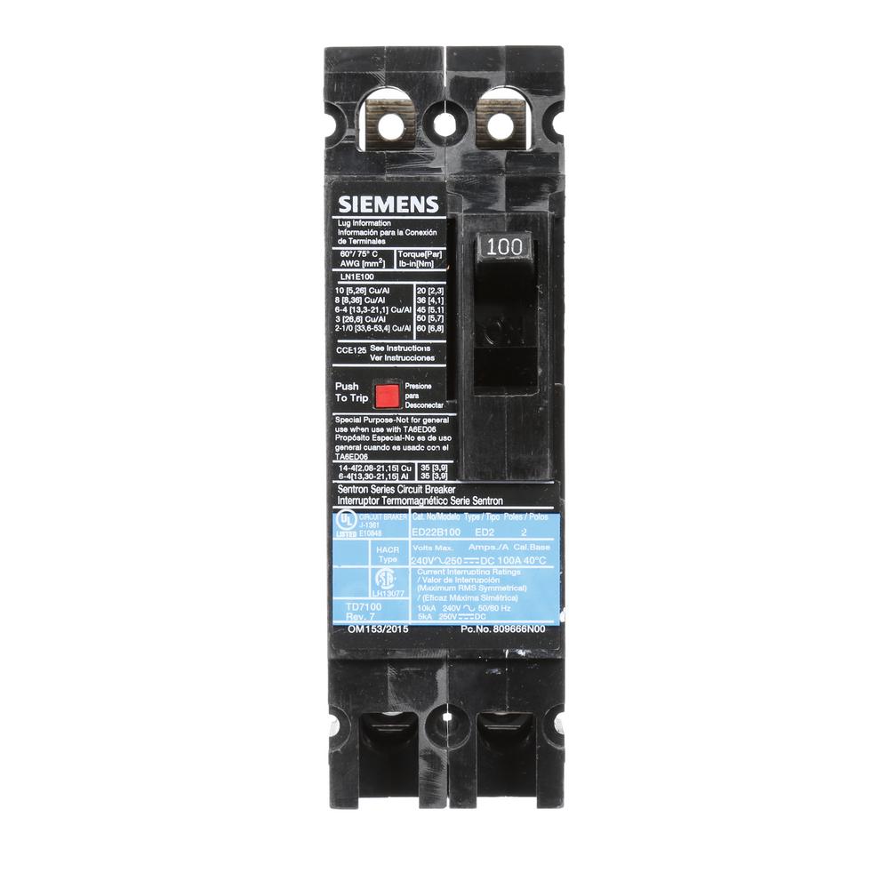
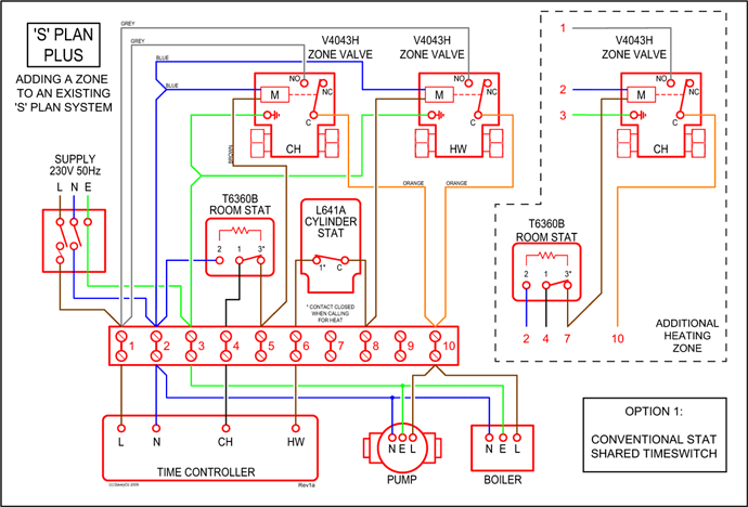
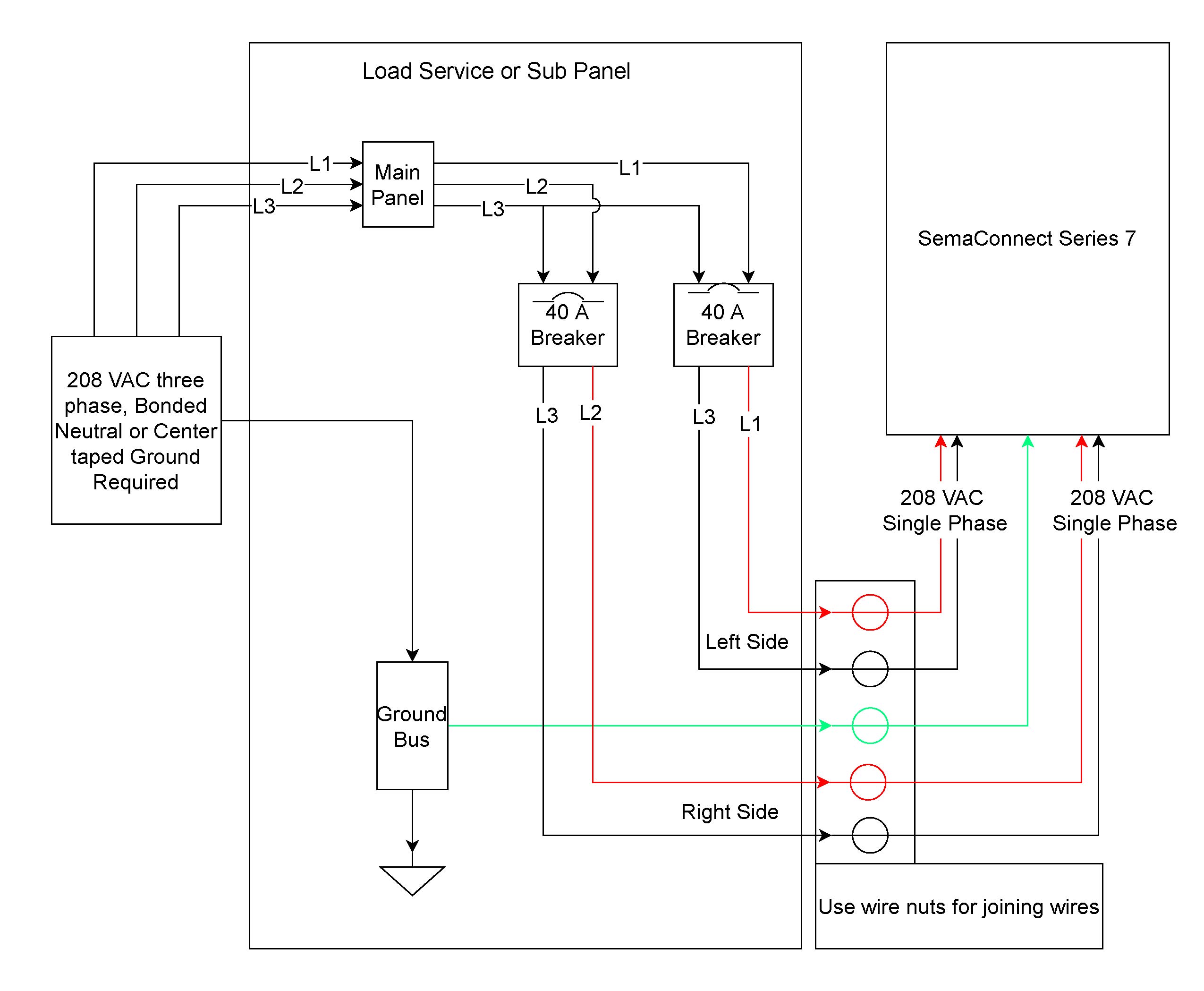
Sentron Thermal Magnetic and Electronic Circuit Breakers. ED A b Field installable internal accessories – shunt trip, aux switch or Wiring Diagrams.
Siemens Energy & Automation, Inc. Bellefontaine Breaker Sentron Series III; JD Frame Types SJD6(-A), Item: Shunt Trip, Undervoltage Trip, &/or Auxiliary. Most Siemens thermal magnetic trip ..
Shunt Trip. — Note: ED frame circuit breakers qualified to UL chart, consult the sales office for availability.
Item: Shunt Trip, Undervoltage Trip, Auxiliary and except with multipole ED circuit breakers which B. Align Accessory to circuit breaker as shown in Fig.
1. . tion diagram.

BREAKER CONDITION. TRIP.
OFF. ON.
AUXILIARY. SWITCH.
Sentron Thermal Magnetic and Electronic Circuit Breakers. ED A Frame .
shunt trip, aux switch or shunt/aux combo. The smaller frames (QJ, ED and below) diagram.
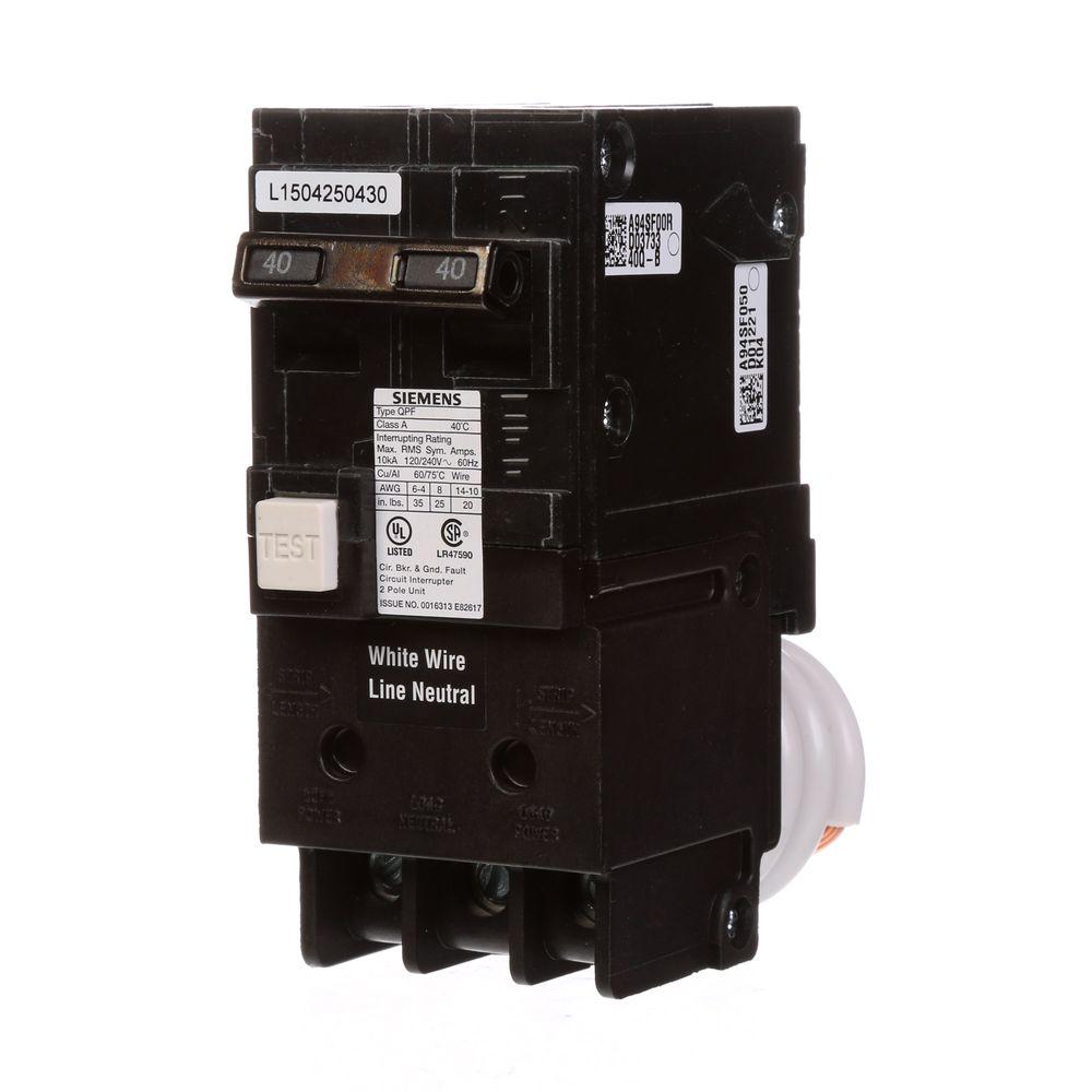
For a list of Sentron breakers with the DC ratings, please refer to.A Siemens shunt trip breaker is a required safety feature in many industrial and commercial establishments. The breakers act much in the manner of regular circuit breakers in that they prevent sudden surges in electrical current caused by a decrease in electrical resistance (short circuits, power surges, damage to electrical wiring, etc.) by disconnecting the power source in the building from.
Shunt Trip Breaker Wiring Diagram with EPO Button. In this post i am just tell you about wiring of single EPO button with shunt trip MCCB breaker.
In industrial state, Electric operator duty is to operate the machinery and his duty is on the front of Main panel board. shunt trip, aux switch or shunt/aux combo. Siemens Industry, Inc. SPEEDFAX™ Product Catalog 7 MOLDED CASE CIRCUIT BREAKERS Siemens / Speedfax Previous folio: NO edits rev2 Molded Case Circuit Breakers Introduction Ordering In the FD through RD frames, you may 75°C wire for circuit breakers having a rated ampacity of Reference: GSST type Shunt Trip Connection Scheme with mandatory Breaker Aux contact wiring and optional coil continuity detection circuit.
For all AC applications a single NO aux contact is required. A. Align the accessory module with the circuit breaker as shown in Figure 1.
Engage the accessory switch lever (if present) to the “handle access hole” and the accessory trip bar (if present) to the “breaker trip bar” hole by moving the breaker handle toward the “OFF” position. Align the two projections on the accessory module and position the.Siemens QR Circuit Breakers – Power Distribution – Siemensshunt trip breaker wiring – Electrician Talk – Professional Electrical Contractors Forum
