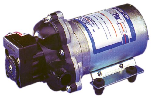
Shurflo Series Parts List. 7.

1. 2.
3. 6. 5.
4. 1.
2. 3.
4. 5. 6.
7 Comes with UH Shurflo. Showing 1 models. View Parts; View Manuals.

models. http://www.
schematron.org Choose a Manual. Interactive Parts Diagram · Manual.

Shurflo. Showing 1 models.
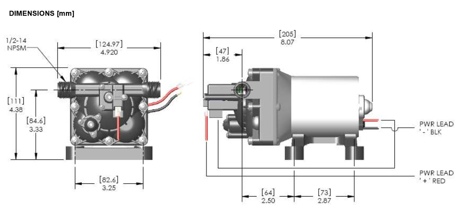
View Parts; View Manuals. models. http://www.

schematron.org Choose a Manual. Interactive Parts Diagram · Manual.
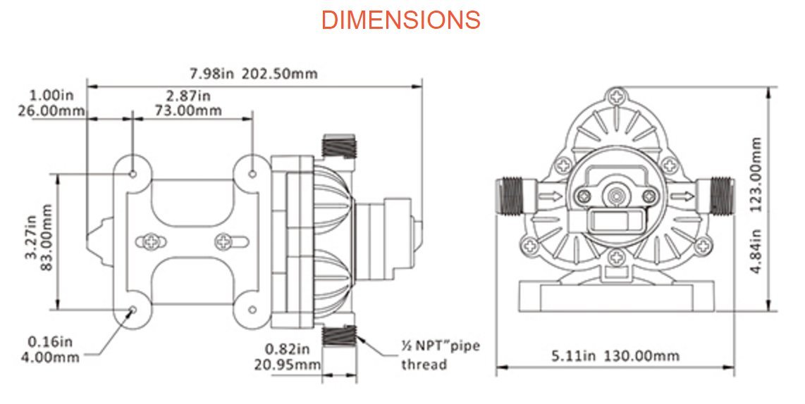
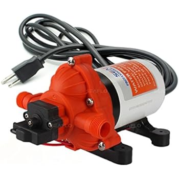
SHURflo offers various pumps models for different applications. .
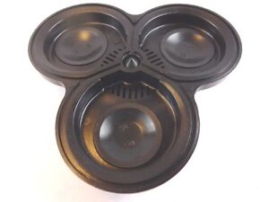
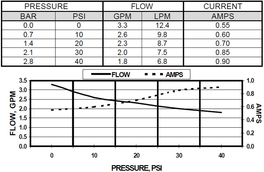
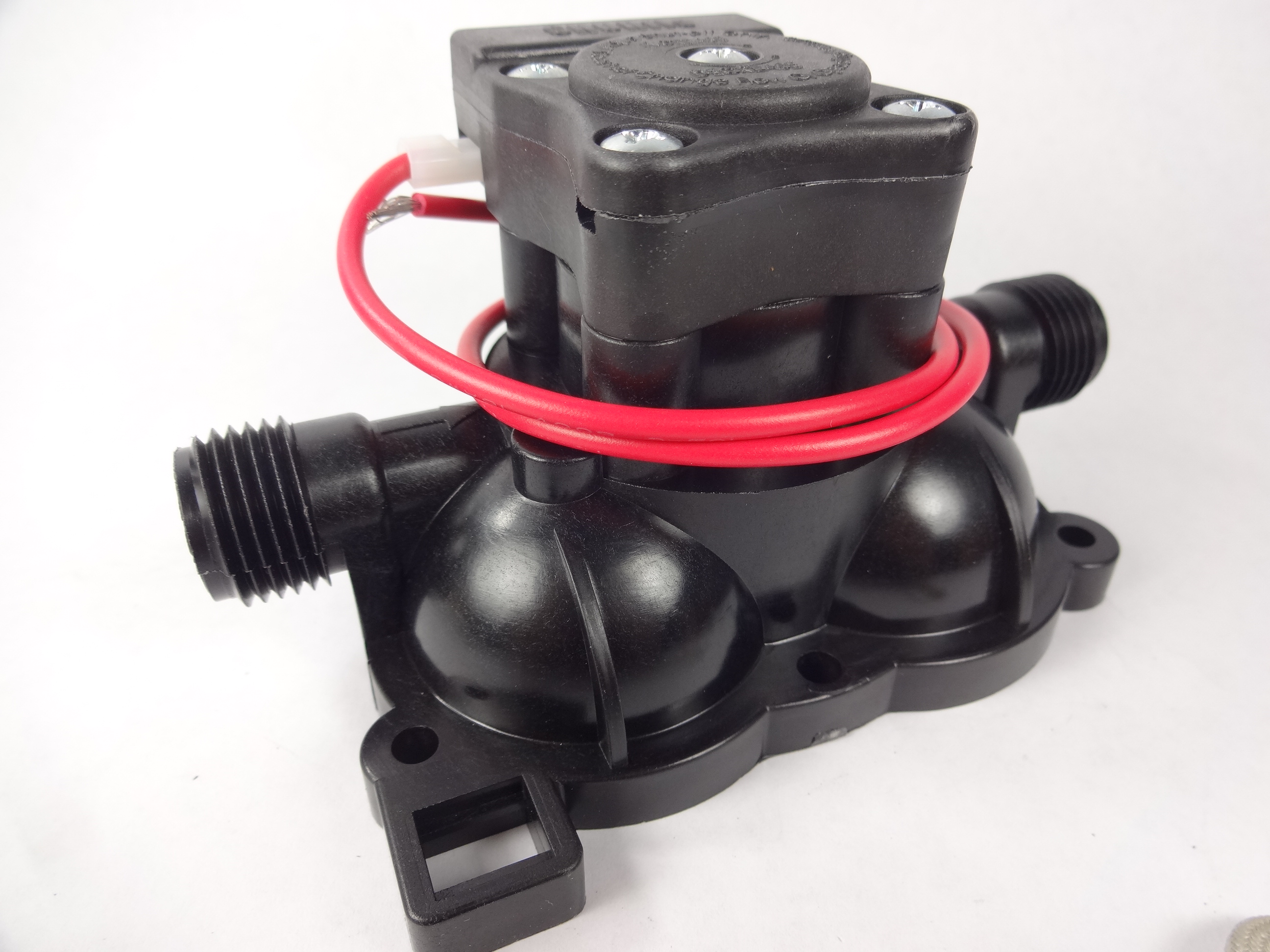
and ampere load on the circuit, wire may need to be heavier than indicated by the chart. These SHURflo Series diaphragm pumps deliver Notes are used to notify of installation, operation, or . need to be heavier than indicated by the chart.Shurflo Upper Housing Repair Kit This item corresponds to part #3 in the diagram. upper housing repair kit for standard, Premium, and other pumps.
This kit covers the following pumps. I have a Shurflo , gpm pump on my motor home which is 3 years old, over the weekend it stopped working.
I took it out and check my Jensen Micro switch and there is juice to the pump but it won’t work, however when I took out the pump and hot wired directly to . Shurflo Series Parts List 7 1 2 3 6 5 4 1 2 3 4 5 6 7 Complete Bypass/ Drive/Impeller Model Pumphead Switch Check Valve Upper Non Bypass Diaphragm.

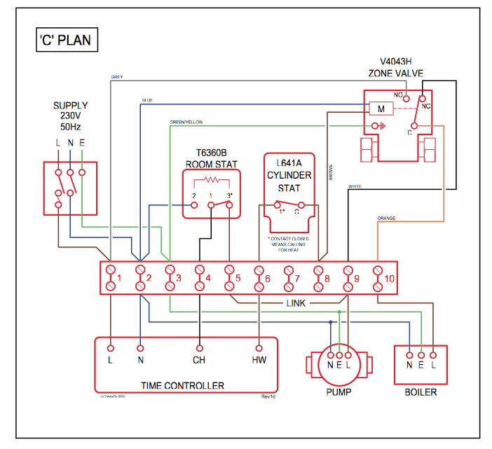
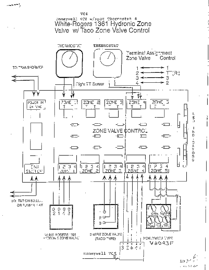
Shurflo Pump Wiring Diagram – Well Water Tank Diagram ~ you are welcome to our site, this is images about well water tank diagram posted by Ella Brouillard in Well category on Oct 29, You can also find other images like images wiring diagram, images parts diagram, images replacement parts, images electrical diagram, images repair manuals.
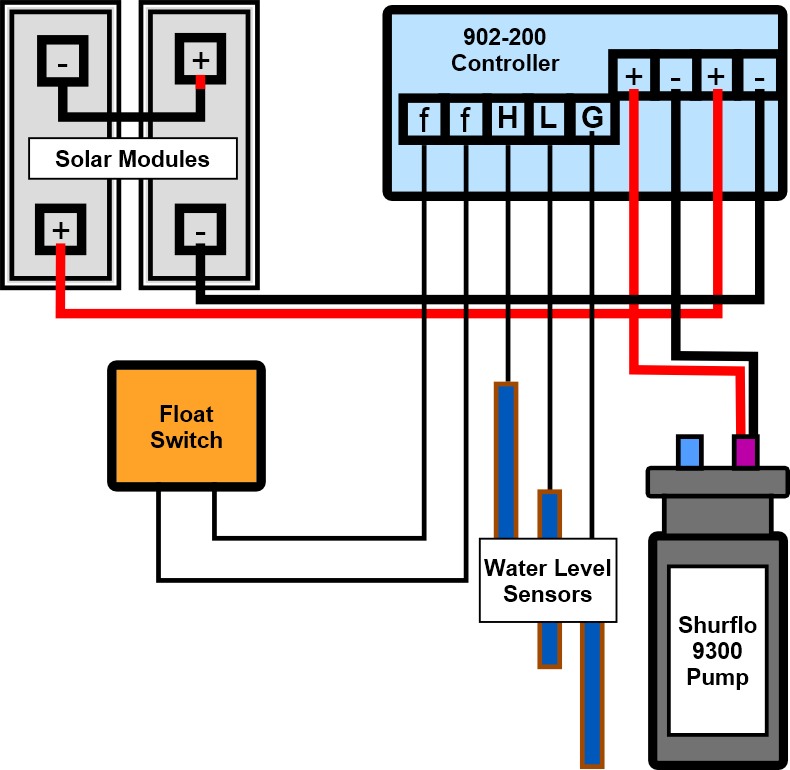
Installation Manual for the SHURflo LCB – G Pump Controller The “LCB – G” pump controller is a high quality DC power converter designed as an interface between a DC (Solar)-Pump (e.g.
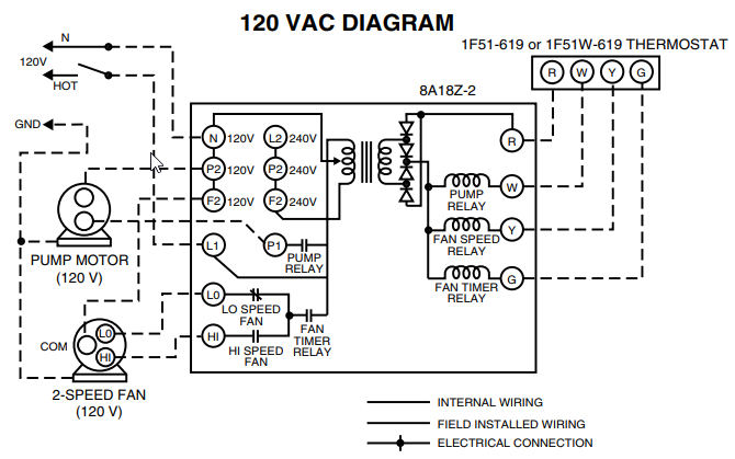
SHURflo particular system configuration and the wiring diagram is given.SHURflo Pump Repair & Rebuild Valve Assembly NEW | eBaySOLVED: Wiring for shurflo – Fixya