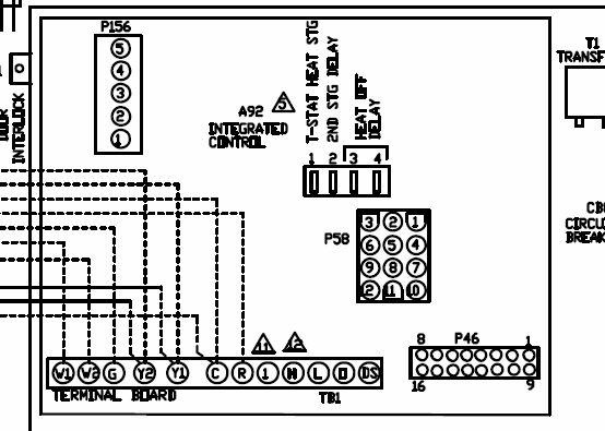
SINAMICS G Converters with . Wiring the terminal strip. .
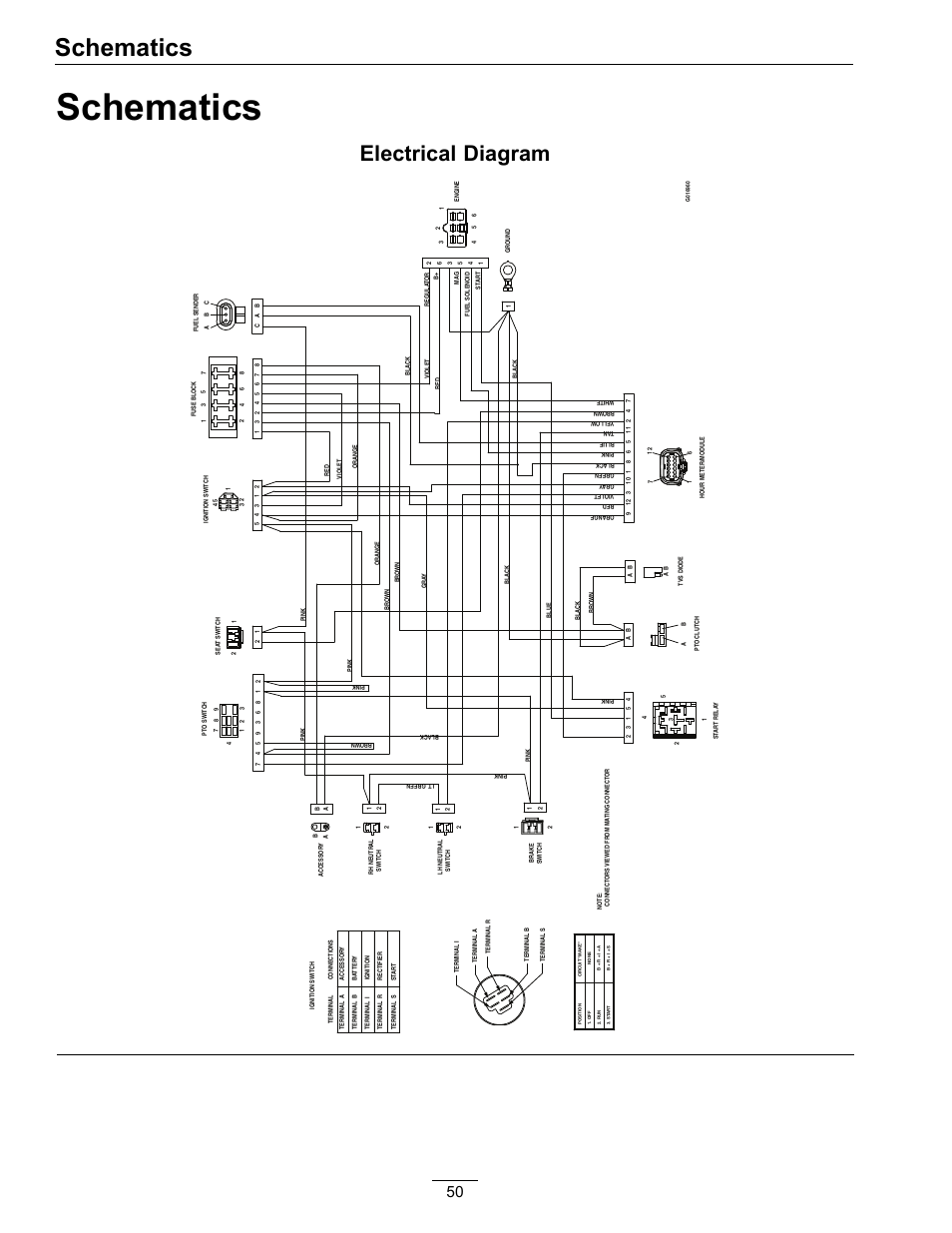
This manual describes how you install a SINAMICS G converter with CUS-2 Control. Wiring Sequence.
.. The SINAMICS G inverter has been designed for the accurate and efficient control of the FSF.
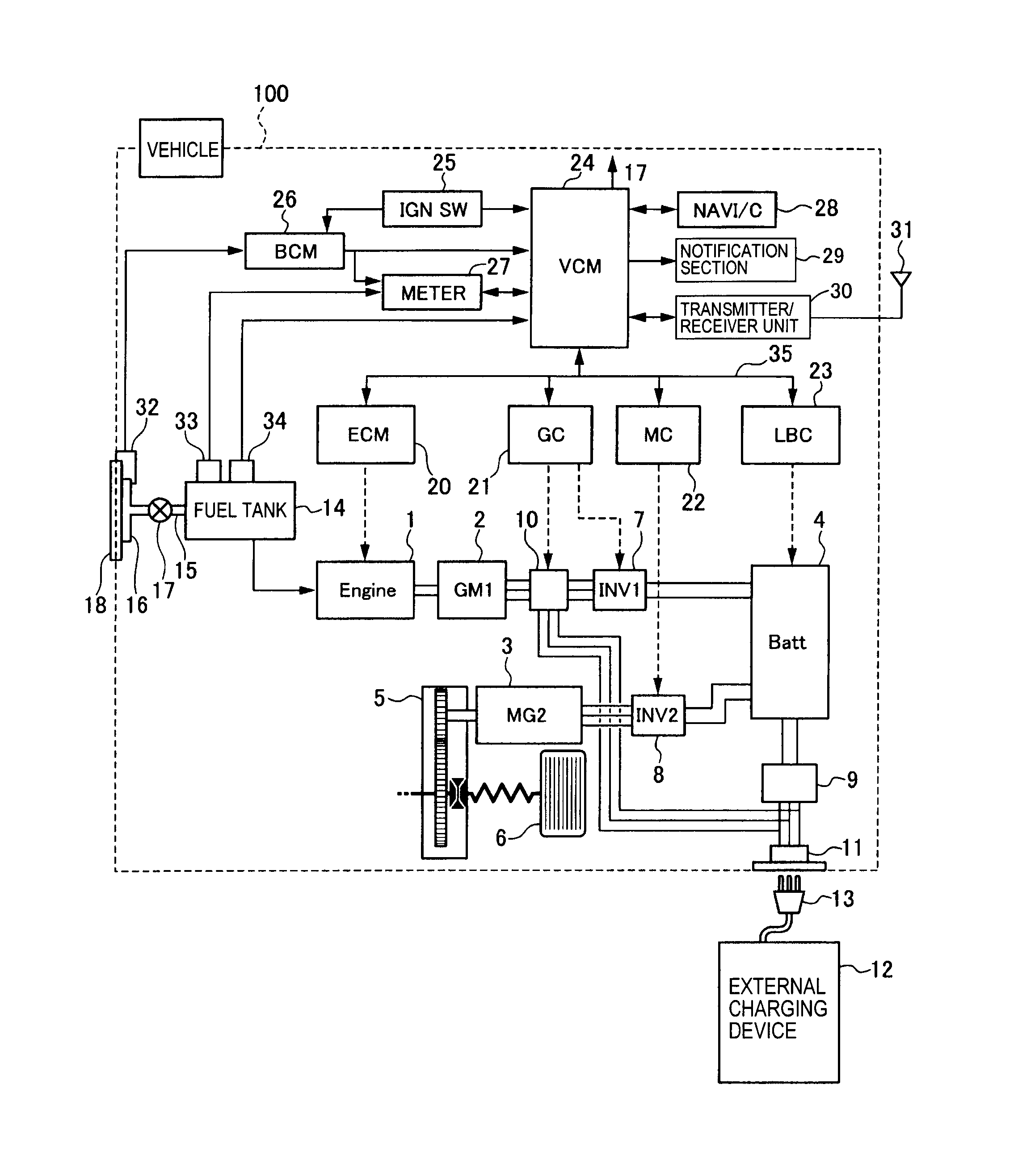
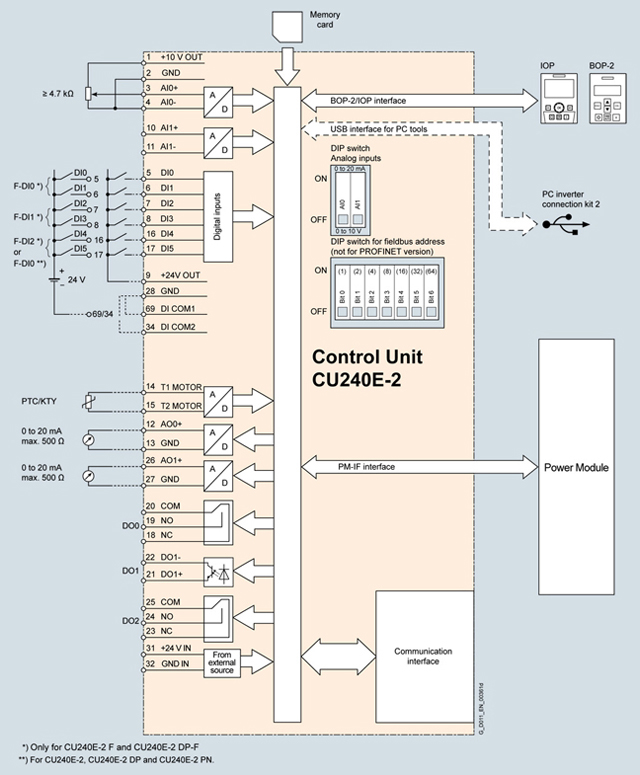
Figure Block diagram PM Siemens Sinamics G Manual Online: Wiring Diagrams. Overview Since the purpose of the IOP Wizards are to guide the user through the setting-up and. The SINAMICS G fail-safe frequency inverter provides four safety functions, certified and expense involved in planning and wiring the system are sig- nificantly reduced.
□Integration. Connection diagram for CUE Control Unit.
ON. Siemens Sinamics G Manual Online: Wiring Diagrams.
Overview Since the purpose of the IOP Wizards are to guide the user through the setting-up and.The SINAMICS ® G family of closed-loop vector drives offers high levels of integrated safety, energy savings, and network connectivity. Available in ½ to HP, this modular and scalable standard drive may be configured in a wide variety of designs to meet many industrial drive applications.
01/ SINAMICS SINAMICS G CUB/E-2 Control Units List Manual Valid for Firmware version Control units CUB-2 CUB-2_DP CUE-2 SINAMICS G Control Units CUB-2/CUE-2 List Manual (LH11), 04/, A5EB AA 9 1 Fundamental safety instructions Industrial security Industrial security Note Industrial security Siemens provides products and solutions with industrial security functions that support the.
SINAMICS G Inverter chassis units kW to kW ( hp to hp) SINAMICS G chassis units Siemens D · 3/3 3 Overview (continued) Modularity SINAMICS G is a modular converter system comprising a.

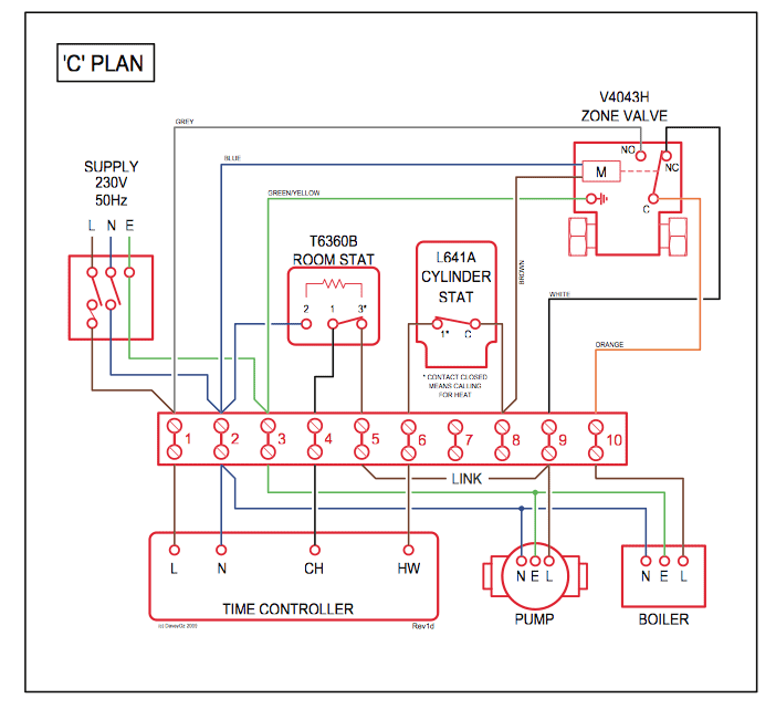
Wiring diagrams for Siemens NEMA contactors and starters.Sinamics G Wiring Diagram – schematron.orgSINAMICS G Built-in Units – SINAMICS G Built-in units – Siemens