
Products Westminster. 50 TECHNOLOGY DRIVE, WESTMINSTER, MA.
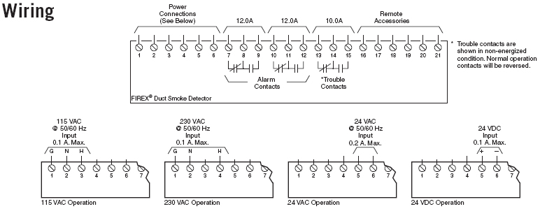
TITLEFIELD WIRING DIAGRAM. EQUIP SMOKE / HEAT DETECTORS. DWG NO.
The Duct Detectors are designed for use in ducts where the air velocities are from to feet . SDDUCTR WIRING DIAGRAM.
SUPPLY VOLTAGE. The Duct Detectors are designed for use in ducts where the air velocities are from to feet .
SDDUCTR WIRING DIAGRAM. SUPPLY VOLTAGE. The Duct Detectors are designed for use in ducts where the air velocities are from to feet .
SDDUCTR WIRING DIAGRAM. SUPPLY VOLTAGE.
The Smoke Detector has two chambers, an NOTES: 1. Refer to wiring diagrams provided with system for proper panel connections ().

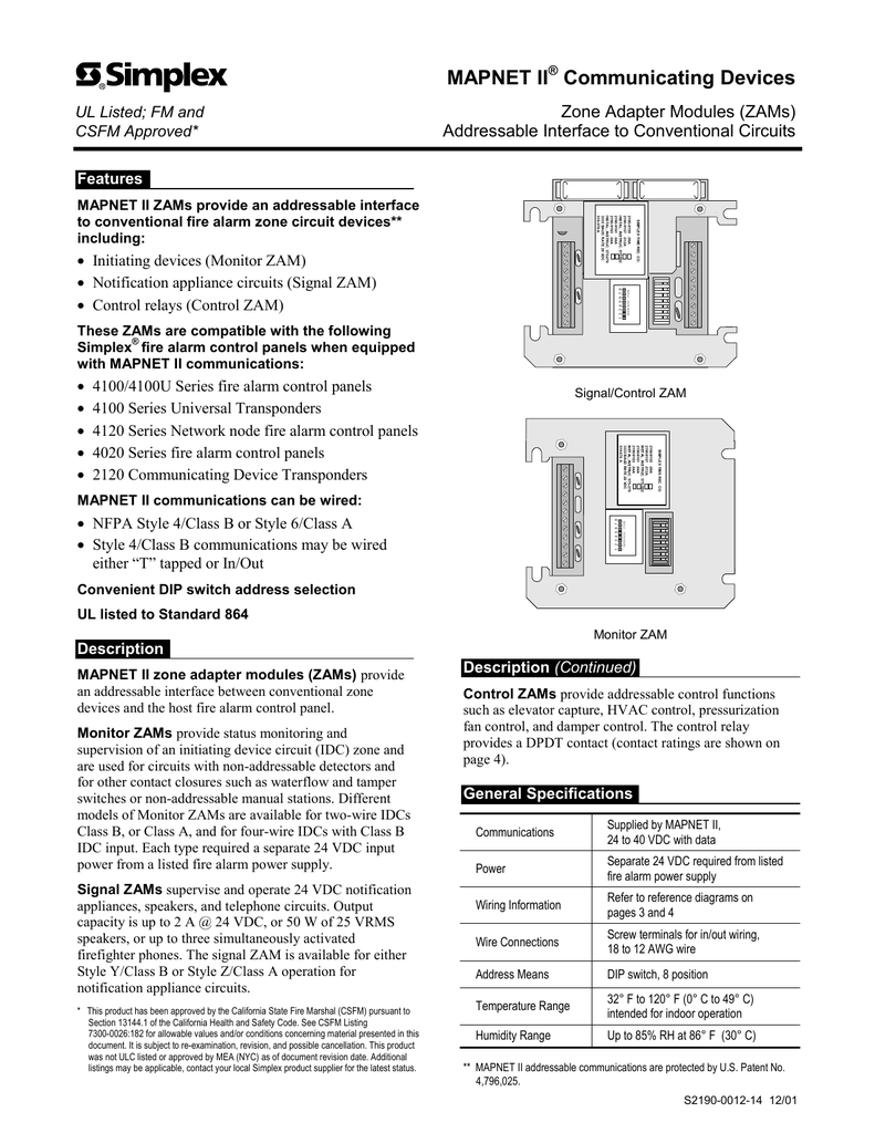
2.The duct smoke detector latches into alarm state when an alarm occurs. The D and D4P LEDs indicate the status of power, maintenance, trouble, and local alarm conditions. Aug 29, · 2 wire fire alarm wiring diagram,2 wire smoke detector wiring diagram,simplex 2 wire smoke detector wiring diagram, Wiring Basics Article 5 for DIY Alarm Systems img source: schematron.org duct smoke detector wiring diagram – fharatesfo img source: .
Title: Pro/ENGINEER – D Author: jvallee Created Date: 1/18/ AM. Simplex® compact air duct smoke sensor should this duct smoke detector be used or regarded to be a substitute for the building’s Fire alarm and Wiring terminals Gaskets (supplied) Conduit (by others) Stationary baffle (built-in) Smoke sensor, mounted.
Duct detector addressing is critical since the CDT and the , , or System report alarms and troubles per duct detector rather than per zone of duct detectors. Each duct detector has a unique address.
This address is associated with a custom label which identifies its physical location within a .Do you have a wiring diagram for a Simplex 4-wire – FixyaRead +Duct+Housing+Installation+schematron.org