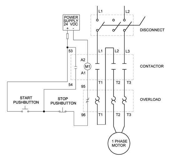
A single phase motor starter is a device that controls the starting and stopping of a single phase motor. It is used in various applications such as pumps, compressors, fans, and conveyors. The motor starter includes a contactor, overload protection, and a control circuit. The contactor is the main component that connects and disconnects the motor from the power source. The overload protection protects the motor from overheating and excessive current. The control circuit provides the necessary voltage and current to operate the contactor and overload protection.
Wiring a single phase motor starter involves connecting the main power supply to the terminals of the contactor and overload protection. The power supply is usually connected to the contactor through a set of terminals labeled L1 and L2. The overload protection is connected in series with the motor and is responsible for monitoring the motor’s current. If the current exceeds a certain threshold, the overload protection opens the circuit and stops the motor.
In addition to the main power supply, a single phase motor starter also requires a control circuit to operate the contactor and overload protection. The control circuit includes a start and stop button, a control transformer, and control wires. When the start button is pressed, it provides voltage to the control circuit, which energizes the contactor and closes the circuit. This allows the current to flow through the motor, starting it. When the stop button is pressed, it interrupts the voltage to the control circuit, which de-energizes the contactor and opens the circuit. This stops the motor.
Overall, understanding the wiring diagram of a single phase motor starter is essential for proper installation and operation. It ensures that all the components are correctly connected and functioning, providing reliable and safe operation of the motor. It is important to follow the manufacturer’s instructions and consult an electrician if unsure about the wiring process.
Overview
In the field of electrical engineering, single-phase motors are widely used for various applications. A single-phase motor starter is an essential component that controls the starting and stopping of the motor, ensuring its safe and efficient operation.
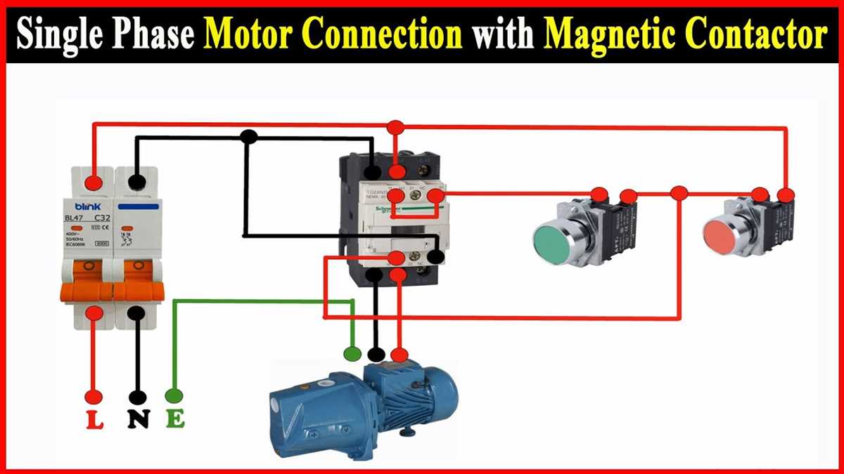
A single-phase motor starter wiring diagram provides a visual representation of the electrical connections and components involved in a motor starter circuit. It helps professionals and enthusiasts understand the wiring configuration and make necessary adjustments or troubleshooting.
The wiring diagram typically includes symbols for various components such as the motor, starter, overload relay, contactor, and switches. These symbols are used to indicate the electrical connections and the flow of current within the circuit.
The wiring diagram also shows the control circuit, which includes the start and stop buttons, as well as other control devices such as timers or protective relays. These control devices ensure that the motor starts and stops at the desired times and protect it from overloads or faults.
Understanding the single-phase motor starter wiring diagram is crucial for electricians, technicians, and engineers working with single-phase motors. It allows them to properly install, maintain, and troubleshoot motor starter circuits, ensuring the efficient and safe operation of the motors in various applications.
Understanding Single Phase Motors
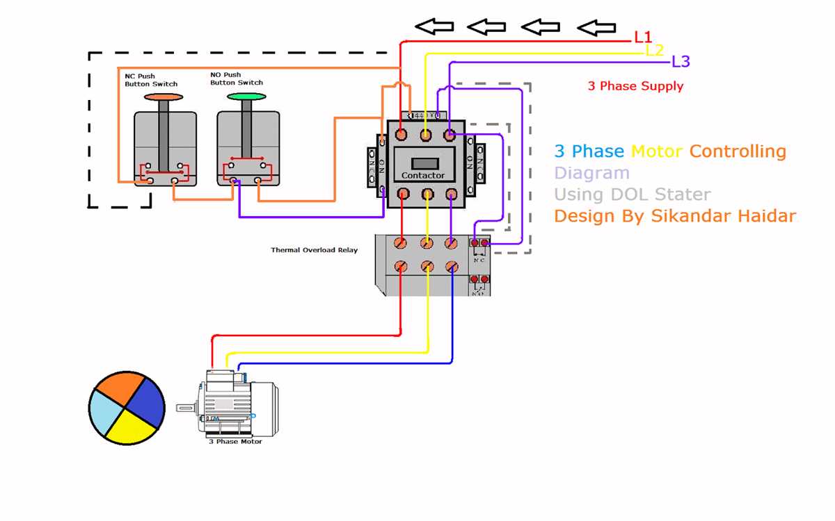
Single phase motors are commonly used in residential and small commercial applications. They are simple and cost-effective solutions for powering various devices such as fans, pumps, and compressors. Understanding how single phase motors work and how they are wired is crucial for their proper installation and operation.
Types of Single Phase Motors:
- Split Phase Motors: These motors have a start winding and a run winding, which are connected in parallel during startup and switch to a series connection during operation.
- Capacitor Start Motors: These motors use a start capacitor in conjunction with the start winding to provide additional starting torque.
- Permanent Split Capacitor (PSC) Motors: These motors have a run capacitor that is connected in series with the start winding, providing more efficient operation and higher power factor.
Wiring a Single Phase Motor Starter:
When wiring a single phase motor starter, it is essential to understand the motor’s wiring diagram and follow the manufacturer’s instructions. The motor starter typically consists of a contactor and an overload relay. The contactor is responsible for switching the power supply to the motor, while the overload relay protects the motor from overheating.
The wiring diagram will indicate the specific connections for the main power supply, the motor, and the control circuit. It will also show the connections for the start and run capacitors, if applicable. Properly connecting these components and following the specified wiring diagram is critical for safe and efficient motor operation.
Importance of Motor Starters
A motor starter is a crucial component in the operation of single-phase motors. It serves as a control device that allows for safe and efficient starting and stopping of the motor. Motor starters help protect the motor from damage due to overloading, short circuits, and voltage fluctuations, ensuring its longevity and optimal performance.
One key function of a motor starter is to control the flow of electrical power to the motor. It incorporates various protective devices such as thermal overload relays, circuit breakers, and fuses that automatically detect and interrupt the current flow in case of any abnormal or dangerous conditions. This helps prevent the motor from overheating, burning out, or sustaining any other kind of electrical damage.
Motor starters also provide an easy and convenient means of switching the motor on and off. They typically include buttons and switches that allow for manual control of the motor, allowing operators to start or stop the motor as needed. Additionally, motor starters may be equipped with auxiliary contacts that enable remote control and automation of motor operations.
Another important feature of motor starters is their ability to provide motor protection and restart functions. In the event of a power interruption or a voltage drop, the motor starter ensures a safe and controlled restart of the motor once power is restored. It prevents dangerous situations such as motor damage due to sudden power surges or uncontrolled re-energization.
In conclusion, motor starters play a vital role in the safe and efficient operation of single-phase motors. They provide protection against electrical faults, control the flow of power, and enable easy and convenient motor control. By investing in a reliable motor starter, motor operators can ensure the longevity and reliability of their motors, reducing downtime and costly repairs.
Components of a Single Phase Motor Starter
A single phase motor starter is an electrical device used to control the starting and stopping of a single phase motor. It typically consists of several key components that work together to ensure proper motor operation.
1. Contactor: The contactor is the main switching device in a single phase motor starter. It is a heavy-duty relay that controls the flow of electricity to the motor. The contactor has a coil that, when energized, creates a magnetic field that pulls in the contacts, allowing current to flow to the motor.
2. Overload Relay: The overload relay is a protective device that monitors the current drawn by the motor. It is connected in series with the motor and opens the circuit if the current exceeds a predetermined level, protecting the motor from damage due to overheating.
3. Start and Stop Buttons: The start and stop buttons are used to manually control the motor. The start button is pressed to energize the motor and the stop button is pressed to de-energize the motor. These buttons are typically momentary push buttons.
4. Control Circuit Transformer: The control circuit transformer is responsible for stepping down the supply voltage to a lower voltage suitable for the control circuit. It provides power to the control circuit components, such as the contactor coil and overload relay.
5. Capacitor: In some single phase motor starters, a capacitor is used to improve the starting torque of the motor. The capacitor is connected in series with the start winding of the motor and provides a phase shift, allowing the motor to start rotating in the desired direction.
Overall, the components of a single phase motor starter work together to provide reliable and safe control of a single phase motor. By using these components, the motor can be started and stopped smoothly, and protection mechanisms are in place to prevent motor damage in case of overload or other electrical faults.
Wiring Diagram for Single Phase Motor Starter
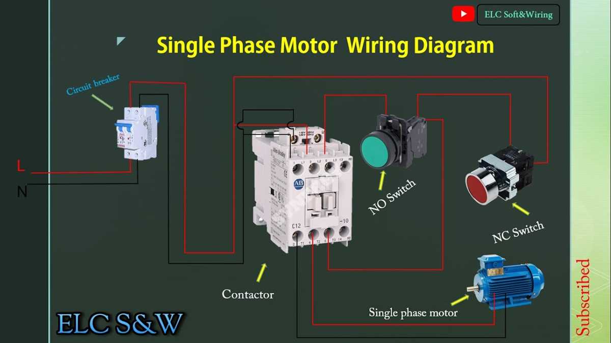
When it comes to wiring a single phase motor starter, it is important to understand the basic components and how they are connected. The purpose of a motor starter is to safely start and stop a motor, providing protection against overload and short circuits.
A typical single phase motor starter consists of three main components: a circuit breaker, a contactor, and overload relays. The circuit breaker protects the motor and wiring from excessive current, while the contactor controls the flow of electricity to the motor. The overload relays monitor the motor’s current and provide protection against overloading.
To wire a single phase motor starter, you will need to start by connecting the power supply to the circuit breaker. The circuit breaker should be sized according to the motor’s current rating and the wiring capacity. From the circuit breaker, a line wire is connected to one side of the contactor coil, while the other side of the coil is connected to the neutral wire. This allows the contactor to be controlled by the circuit breaker.
Next, the overload relays are connected to the contactor and the motor. The overload relays are typically connected in series with the motor’s power supply, so that they can monitor the current flowing through the motor. If the motor draws too much current, the overload relays will trip and disconnect the motor from the power supply.
Finally, the motor is connected to the contactor. One side of the motor is connected to the contactor’s main power terminal, while the other side is connected to the neutral wire. This completes the circuit and allows the motor to be powered on and off by the contactor.
In summary, wiring a single phase motor starter involves connecting the circuit breaker, contactor, overload relays, and motor in a specific manner to ensure safe and reliable operation. It is important to follow the wiring diagram and adhere to electrical safety guidelines when working with motor starters.
Step-by-Step Wiring Instructions
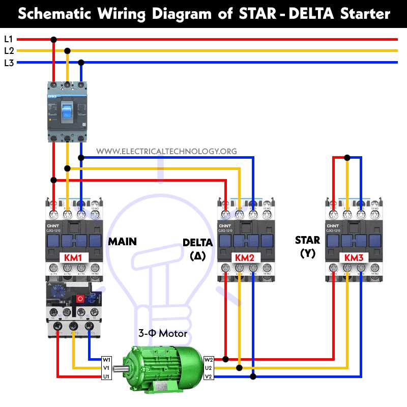
In order to wire a single phase motor starter, follow the steps below:
Step 1: Disconnect the Power
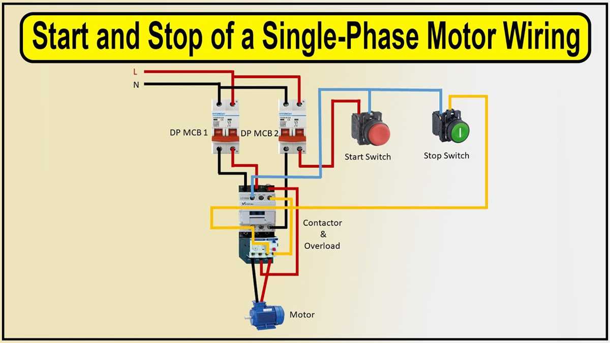
Before starting any wiring, make sure to disconnect the power supply to avoid any accidents. Turn off the circuit breaker or switch that controls the power to the motor.
Step 2: Identify the Motor Wires
Identify the wires coming out of the motor. There will typically be three wires – one for the hot wire, one for the neutral wire, and one for the ground wire. The hot wire is usually colored black or red, the neutral wire is colored white or gray, and the ground wire is usually green or bare copper.
Step 3: Identify the Starter Terminals
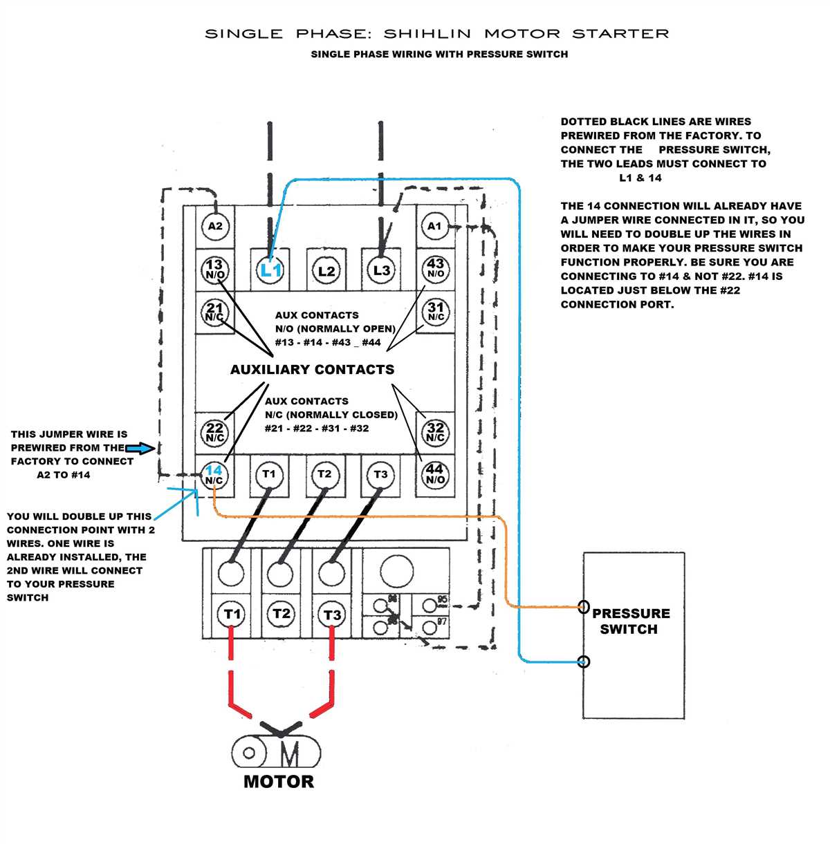
Identify the terminals on the motor starter. There will be six terminals – three for the line side and three for the load side. The line side terminals are labeled L1, L2, and L3, while the load side terminals are labeled T1, T2, and T3.
Step 4: Connect the Motor Wires
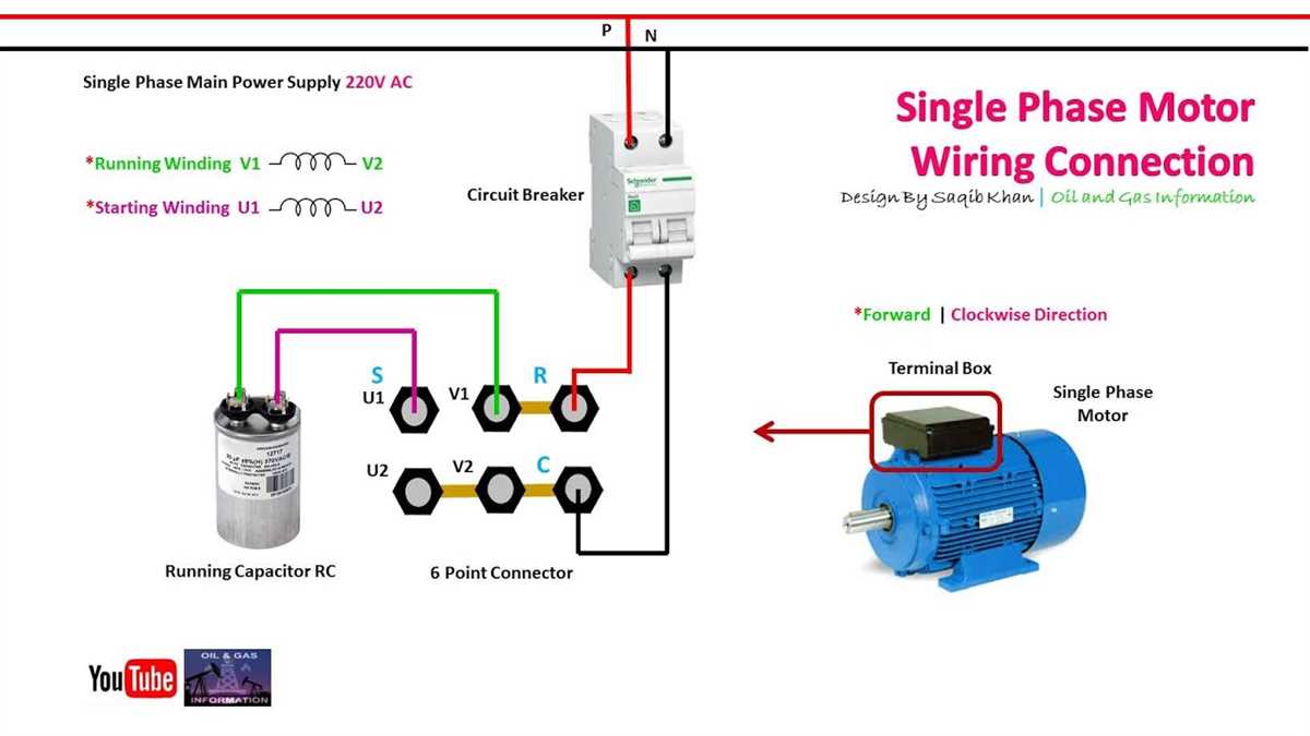
Connect the motor wires to the starter terminals as follows:
- Connect the hot wire (usually black or red) to terminal L1.
- Connect the neutral wire (usually white or gray) to terminal L2.
- Connect the ground wire (usually green or bare copper) to terminal L3.
Step 5: Connect the Load Wires
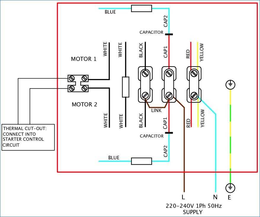
Connect the load wires, which are the wires that go to the motor, to the starter terminals as follows:
- Connect the wire going to the motor’s hot terminal to terminal T1.
- Connect the wire going to the motor’s neutral terminal to terminal T2.
- Connect the wire going to the motor’s ground terminal to terminal T3.
Step 6: Test the Wiring
Once all the wires are connected, double-check the connections to ensure they are tight and secure. Then, turn on the power supply and test the motor starter to see if it is functioning correctly. If the motor starts and runs smoothly, then the wiring is done correctly.
Always consult the motor starter wiring diagram provided by the manufacturer for specific wiring instructions and safety precautions. Follow all safety guidelines and take proper precautions when working with electricity.