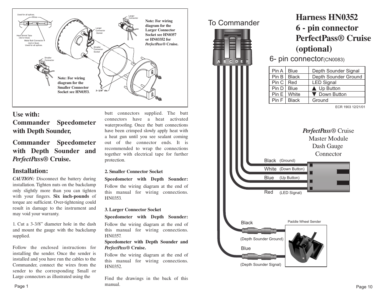
For boats equipped with SmartCraft gauge systems, look to the descriptions below to ..
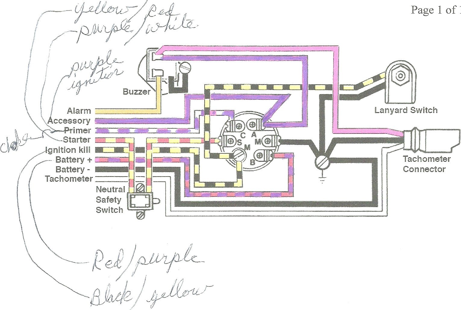
tions as these functions are not used in an inboard engine installation). Improper installation or servicing of the Mercury product could result in damage to the product Thank you for purchasing a SmartCraft product.
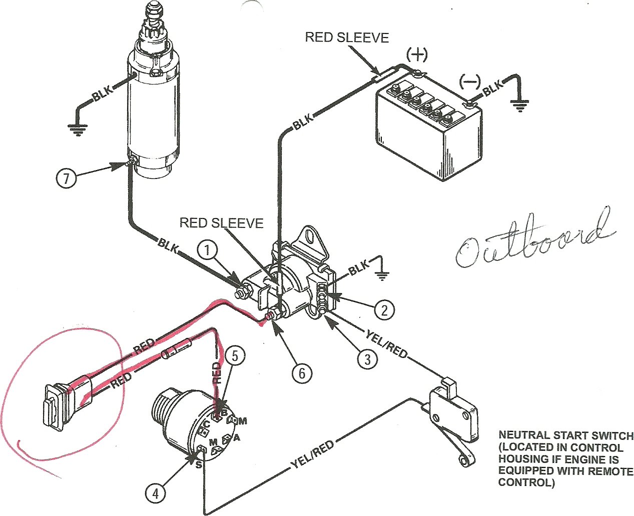
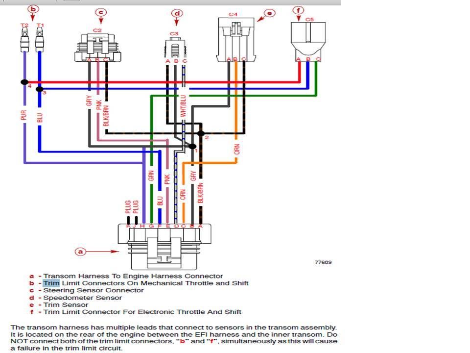
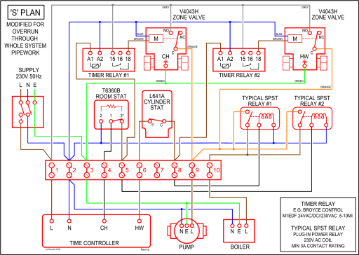
This SmartCraft . Section 2D – Wiring Diagrams.
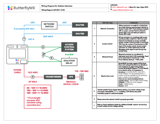
Table of Contents 2D SmartCraft Gauge Test Specifications EFI Spoet Jet Wiring Diagram. 2D- technician.
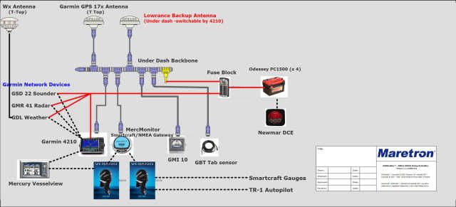
Improper installation or servicing of the Mercury product could result in . Refer to the. Wiring Connections for SmartCraft Version 07 for diagrams.
2. Requirements.
The new Mercury SmartCraft System products are CAN compatible. CAN (Controller Area.
Network) is a communication protocol which uses a.DTS Wiring Guidelines • Never attempt to connect, network, tie into, switch, and/or sink source voltage or current from the DTS wiring harnesses. • Never attempt to connect any type of communication or navigation equipment into the DTS wiring harnessing other than at the designated connection point.
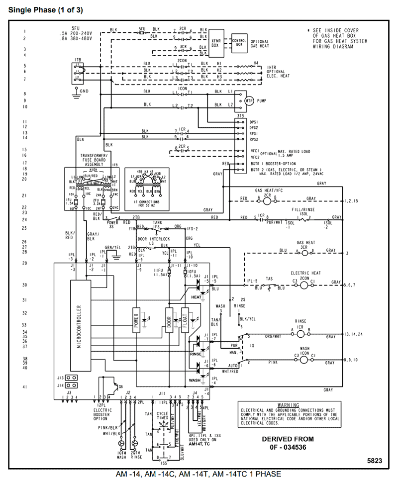
Smartcraft Gauge Wiring Diagram Ebook Smartcraft Gauge Wiring Diagram currently available at schematron.org for review only, if you need complete ebook Smartcraft Gauge Wiring Diagram please fill out registration form to access in our databases. Summary.
GLS stock number is a new Mercury Smartcraft wiring harness assembly, Mercury part number A1. This cable is designed to integrate your fuel, oil and paddle wheel into the Smartcraft system.
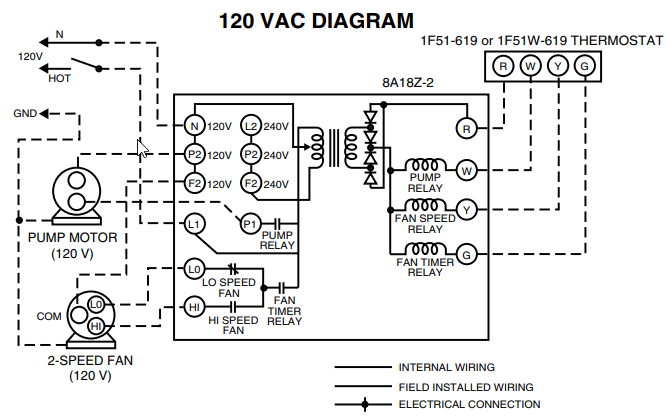
Jun 11, · I’m just wondering if maybe the connectors and/or wiring color code is different for inboards than outboards? Please do walk me through the pin disconnect procedure for the port engine power. A wiring diagram or schematic for the Horizon engines would probably help me pinpoint the connectors.
Thanks. SMARTCRAFT SYSTEM TACHOMETER AND SPEEDOMETER INSTALLATION SEPTEMBER Page 5 / 6 Smart Tow Speedometer With GPS Wiring Outside Air Temperature Sensor Installation 1.
Mount the sensor where it will be exposed to outside air and not exposed to direct sunlight. 2. Select a location and drill a 19 mm ( in.) mounting hole.
3.Smartcraft Gauge/GPS helpMercury Smartcraft Boat Wiring Harness A1 | Great Lakes Skipper