TS1. BRN. YEL.
BLU. BLU. WHT.
BLK. L1.
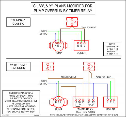
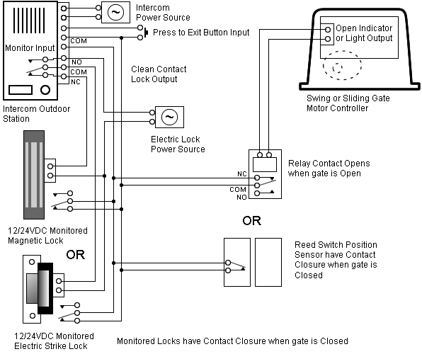
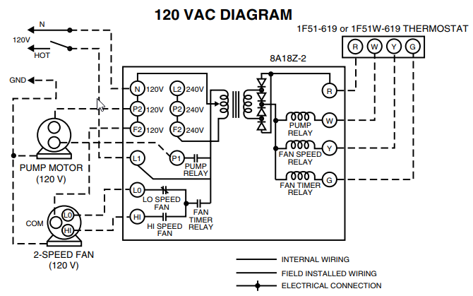
L2. Figure 2: Wiring Diagram. S1 is closed when the damper is closed and S2 is closed when the damper is open.
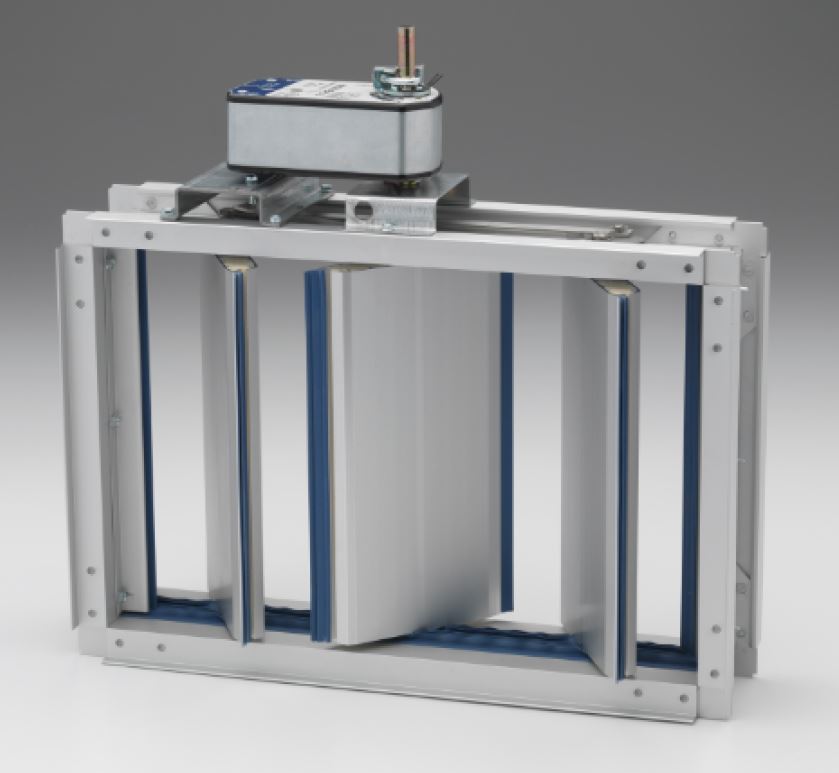
SP Series Installation and Operation Manual. November 3, using the wiring diagram provided with the machine.
See the Electrical Connection data. See wiring diagram. Wire type and wire installation tips.
For most installations, 18 or 16 Ga. cable works well with Belimo actuators. Review job requirements.
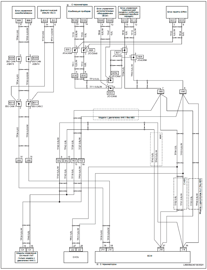
Obtain authorization from the local fire protection authority prior to installation of the SP 2. Verify all parts are included in parts kit (see item list).
House Phone Line Wiring
3. SP Electric actuators to be wired per the National Electric.
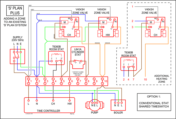
Code (NEC) and local codes. See actuator for wiring diagrams.
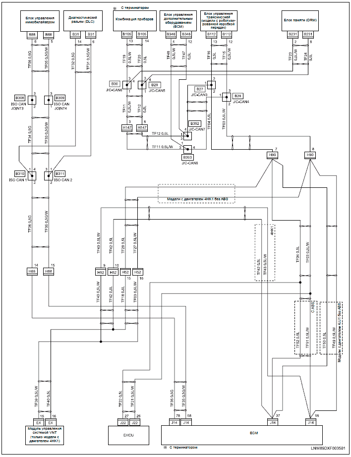
DESCRIPTION. M – Electric Actuator or .Jan 17, · Learn to navigate this system’s wiring circuitry and diagram using current flow analysis, relay and module operation and neutral-switch actuation, such as circuit completion.
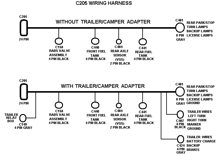
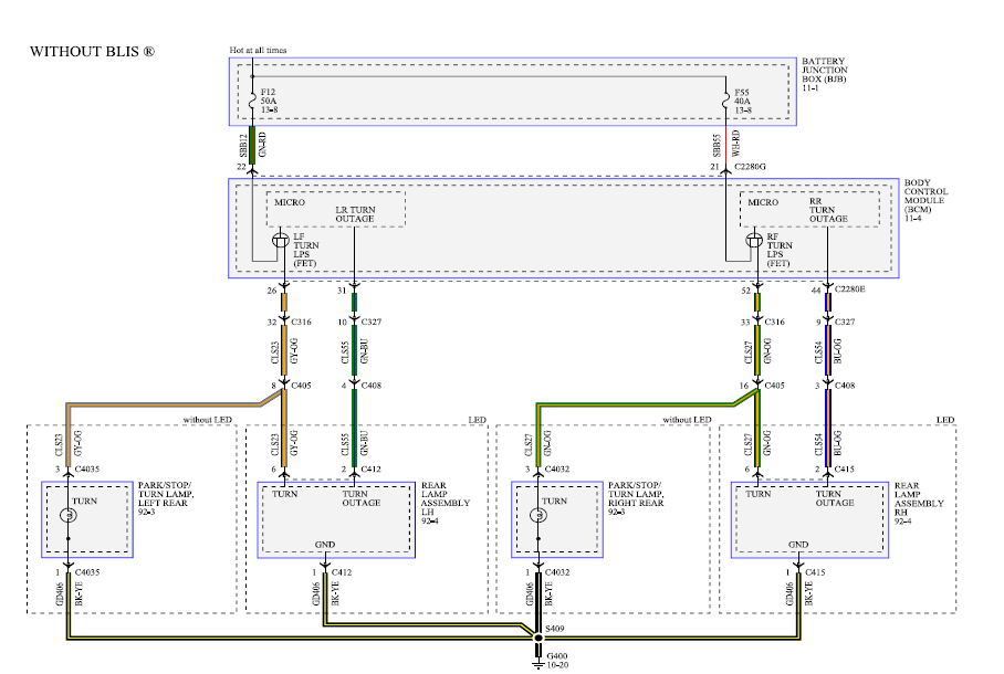
See how the anti. Wiring Diagrams for Car Radio. Car Stereo Wiring Diagrams One of the challenges DIY installers face is finding the correct installation diagrams for car stereos.
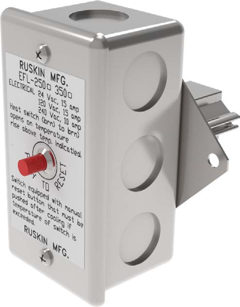
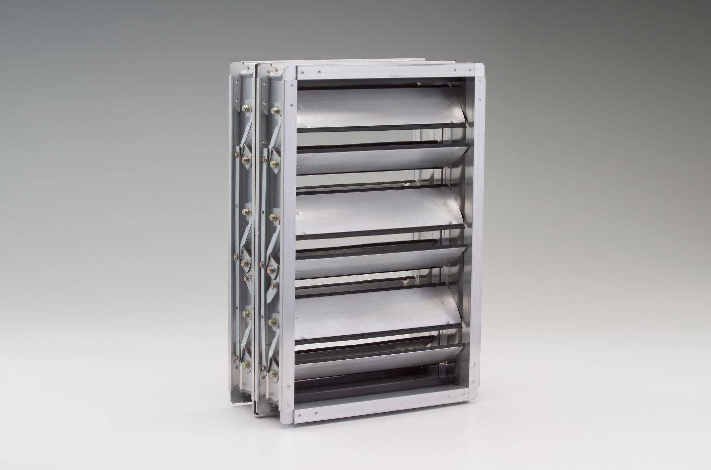
Damper End Switch Wiring
Below I have put together some of the best free sources for car stereo wiring diagrams and wiring colors. Yamaha parts for sale also johnson evinrude parts furthermore lincoln sp parts diagram as well as suzuki uy s step workshop service shop manual scooter uy furthermore further 91 harley davidson xlh sportster clutch cable assembly 86a further parts in addition need help identifying an ez with ezgo marathon wiring diagram go for golf cart .
WIRING INSTRUCTIONS Connections should be made as shown in Figure 4 and indicated in Table 1 *A. White / red (pilot push-to-talk) must correspond with white / black (pilot mic input) as shown. *B.
The blue wire from Pin 3 must be connected to the aircraft radio headphone output- NOT the speaker output. KZ C Wiring diagram.
KZ C1 Wiring diagram, colour. Z B2, G1 Wiring diagram. KZ H1 wiring diagram.
Z B3/G2 wiring diagram. Z G3 Wiring diagram. Z H3 Wiring diagram.
Z A, D Wiring diagram, European. KZ A,D Wiring diagram US, Canada.
KZB2 Wiring diagram. – support | BelimoWiring Diagrams for Car Radio