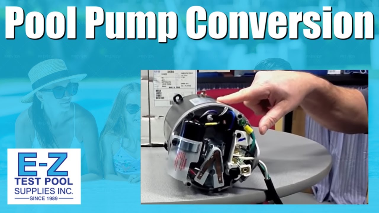
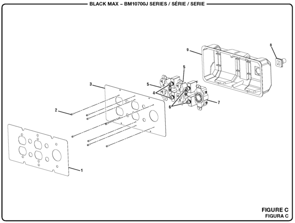
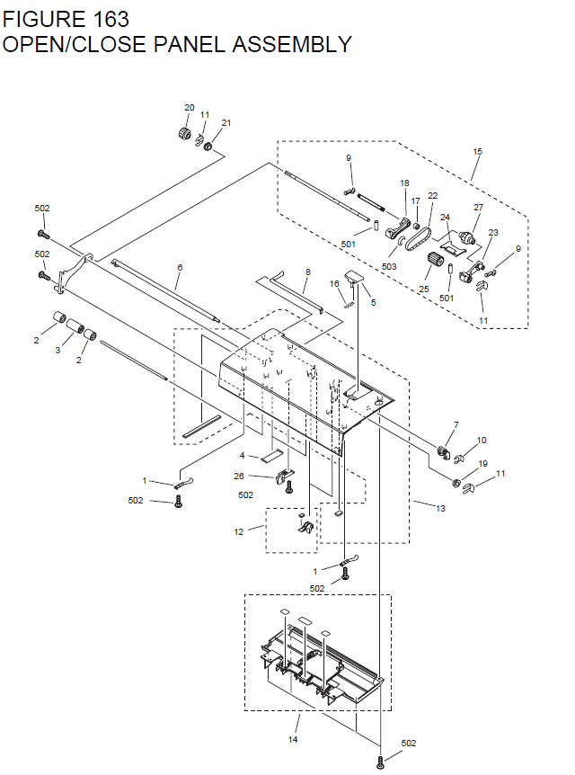
We recommend that all electric motors be installed by a qualified licensed contractor. Disconnect power before attempting to service any electrical apparatus. Parts Diagrams. To view these documents, you will need to download the free Acrobat Reader, which gives you instant access to PDF files.
Please note: The. Cord Set, 3 Wire No. 14 AWG, 6′ long, with plug and terminals.
Item # SPXWA. Hayward pumps are engineered for dependability and performance.
e n c o u n t e red out in the field. This easy to read manual con- tains great illustrations and diagrams for quick re f e rence. Assisting your customers is your job.
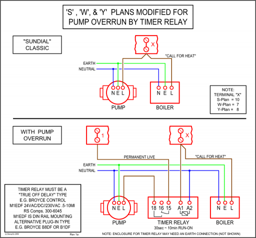
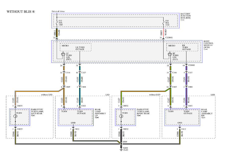
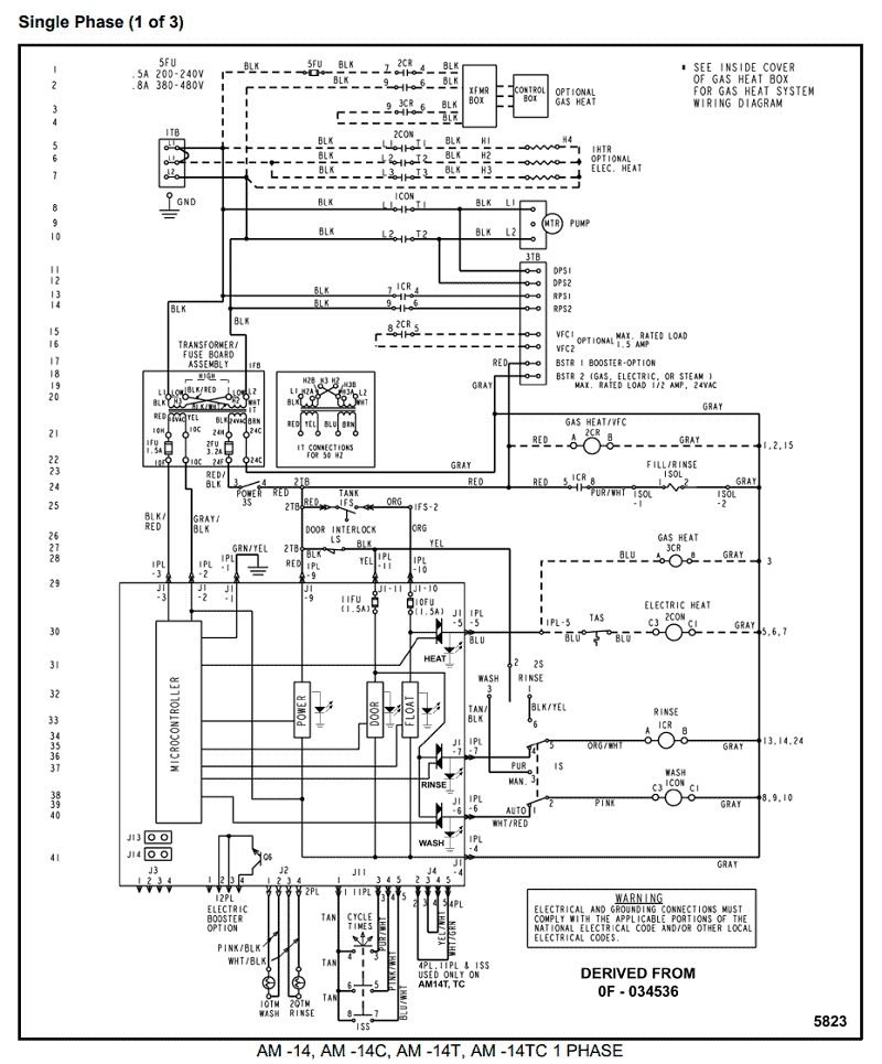
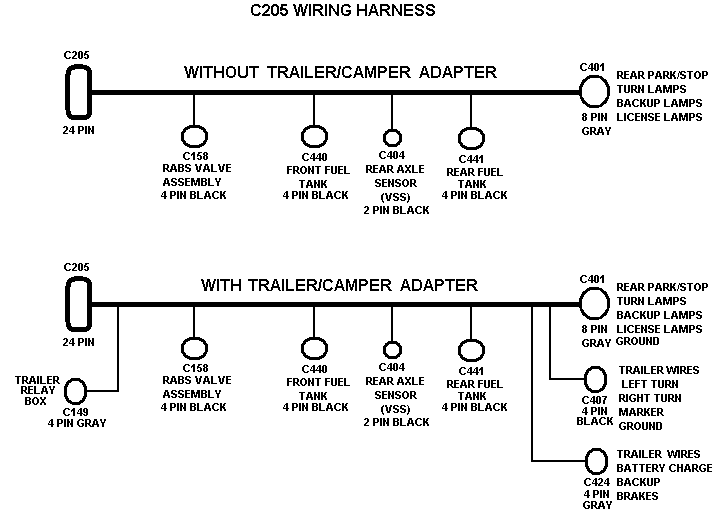
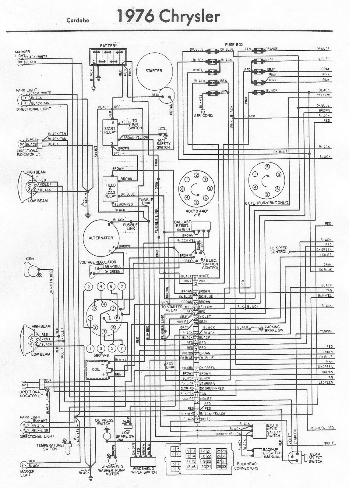
Check the motor diagram for the Low Voltage / High Voltage wiring diagram. An incorrectly installed shaft seal can also produce friction smoke.Find great deals on eBay for ford wiring diagrams. Shop with confidence. • Input Power, Cabinet Tamper, and UPS Fault Input Wiring • Communication Wiring • Reader Wiring • Input Circuit Wiring • Relay Circuit Wiring Cable Routing The cables should run in grounded conduit or at least two feet from AC power, fluorescent lights, or other high energy sources.
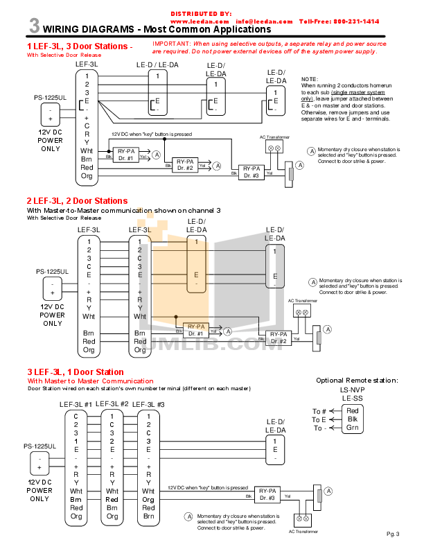
2. Select the appropriate wiring diagram to connect the emergency ballast to the AC ballast and lamp. Make sure all connections are in accordance with the National Electrical Code and any local regulations.
manufacturer 3. Install the test switch through the ballast channel cover of a troffer or through the side of a strip fixture.
Drill a. Motor 2 Hp W/ Switch (SPXZ1ESC, SPZ1ESC) Just got my replacement pump but no wiring instructions. do you have a copy or manual that shows wiring to add the plug.
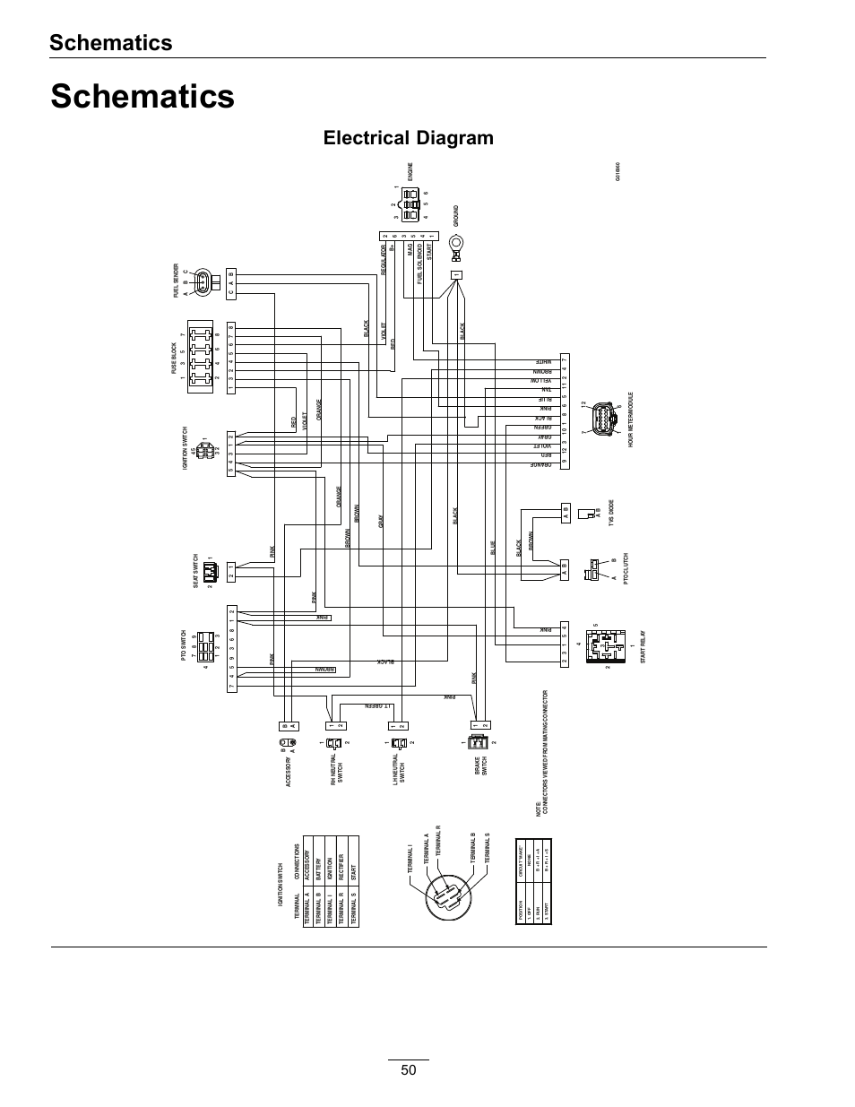
Hi, Michael. A field wiring diagram is located on the motor label.? Price: Install new wiring diagram.
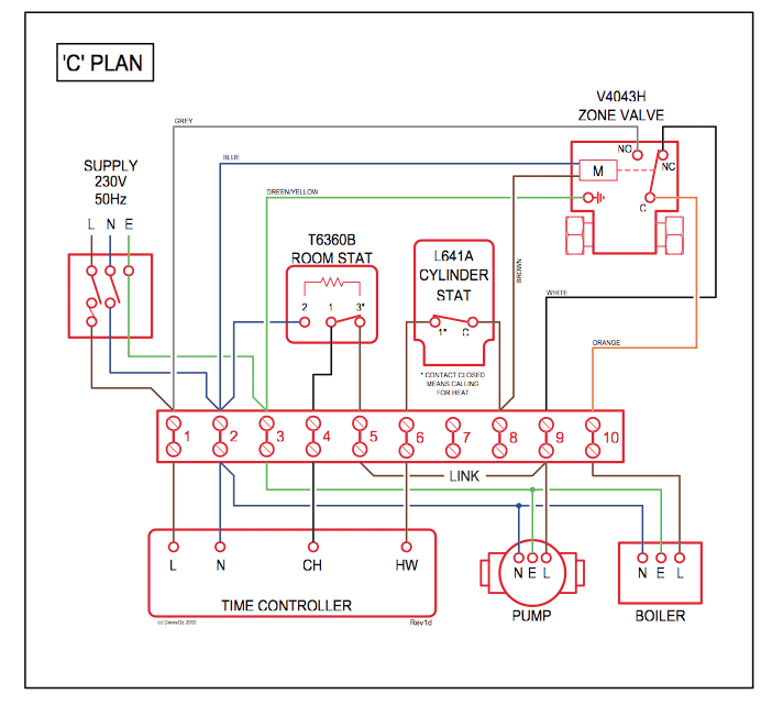
Connect thermostat wires using field-supplied wire nuts. Install control panel access cover.
Reconnect power to units. Verify proper operation of unit.
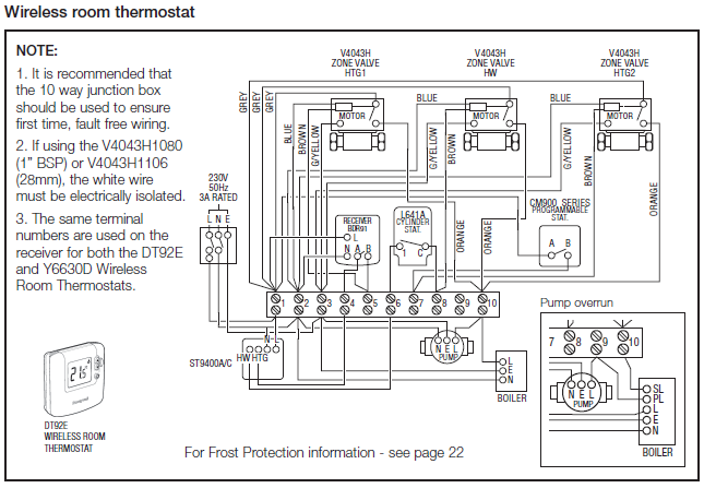
Disconnect electrical power to the AC unit before installing this control. Failure to remove power could result in electrical shock, equipment.Parts Diagrams | Support Center | Hayward Residential and Commercial Pool ProductsHayward Motor 2 Hp W/ Switch (SPXZ1ESC, SPZ1ESC) – schematron.org
