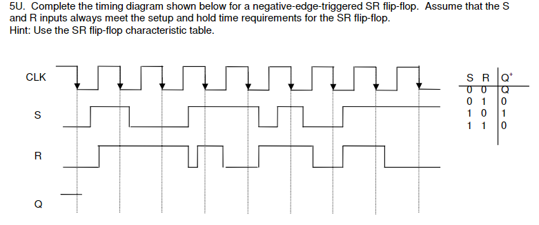
So far, we’ve studied both S-R and D latch circuits with enable inputs.
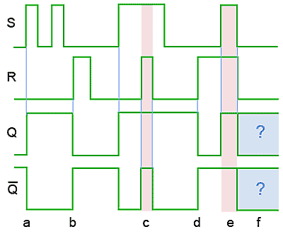
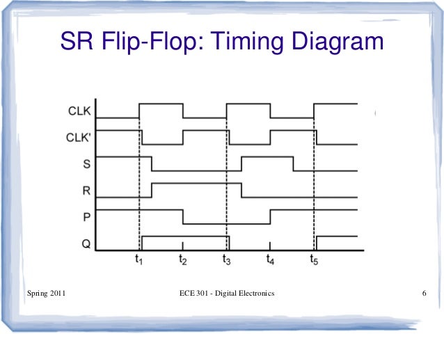
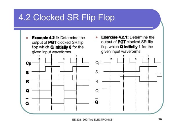
and edge-triggered S-R circuit is more properly known as an S-R flip-flop, and an. Digital Timing Diagram. • Representation of a set of Clocked RS latch D Flip- Flop.
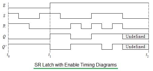
• A D flip-flop can be constructed from an RS flip-flip to allow clocking and. SR Flip Flop and Clocked SR Flip Flop (Digital Electronics)(Hindi) – Duration: 9: physicsanddigitalelectronics , views · Digital Timing Diagram.
• Representation of a set of Clocked RS latch D Flip- Flop. • A D flip-flop can be constructed from an RS flip-flip to allow clocking and. Figure —R-S flip-flop with inverted inputs timing diagram.
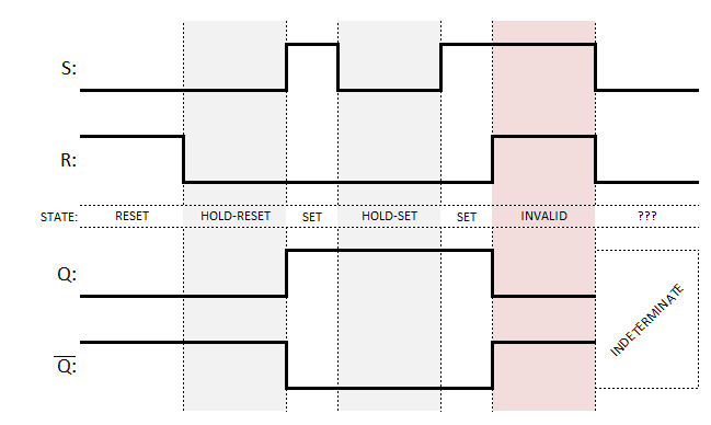
Figure shows two methods of constructing an R-S FF. We can use these diagrams to.Then, a simple NAND gate SR flip-flop or NAND gate SR latch can be set by applying a logic “0”, (LOW) condition to its Set input and reset again by then applying a logic “0” to its Reset input. The SR flip-flop is said to be in an “invalid” condition (Meta-stable) if both the .
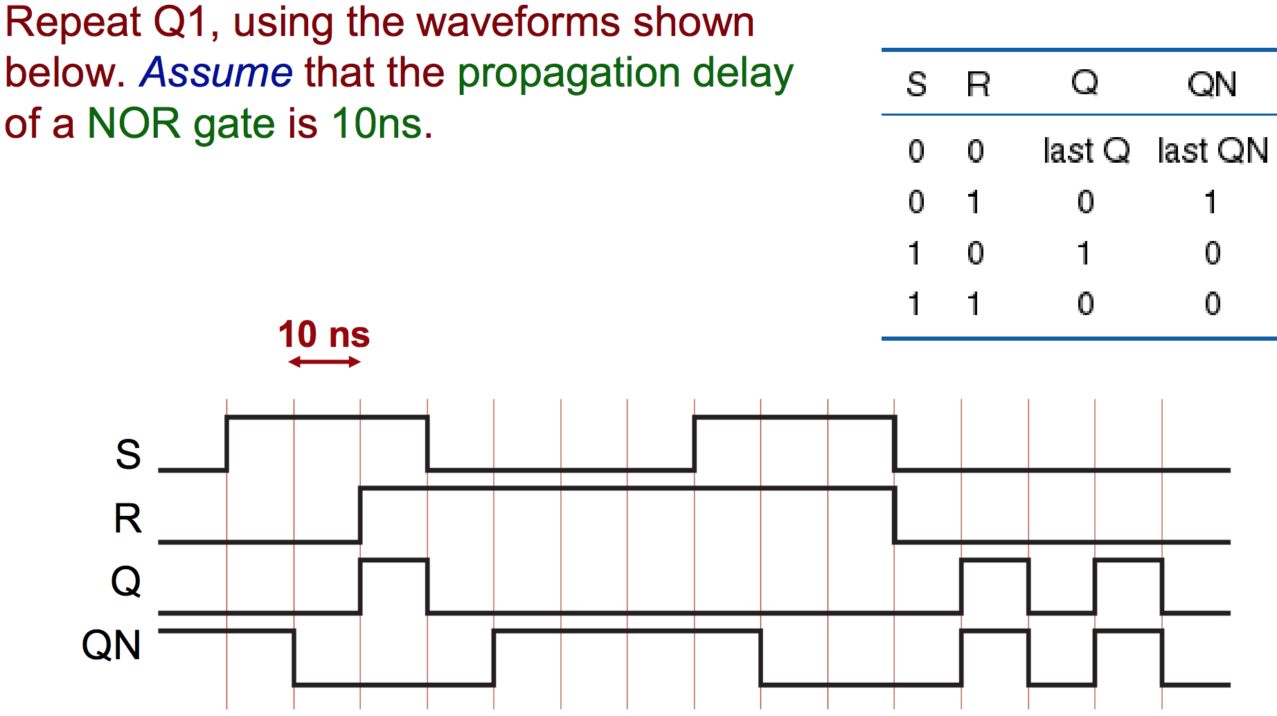
Ask students to identify those regions on the timing diagram where the flip-flop is being set, reset, and toggled. Question 17 Flip-flops often come equipped with asynchronous input lines as well as synchronous input lines.
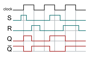
JK flip-flop timing diagram. The JK flip-flop augments the behavior of the SR flip-flop (J=Set, K=Reset) by interpreting the J = K = 1 condition as a “flip” or toggle command.
Specifically, the combination J = 1, K = 0 is a command to set the flip-flop; the combination J = 0, K = 1 is a command to reset the flip-flop; and the. Master-slave flip flop is designed using two separate flip flops. Out of these, one acts as the master and the other as a slave.
The figure of a master-slave J-K flip flop is shown below. From the above figure you can see that both the J-K flip flops are presented in a series connection. The output.
An SR latch, constructed from a pair of cross-coupled NOR gates.. In electronics, a flip-flop or latch is a circuit that has two stable states and can be used to store state information.
A flip-flop is a bistable schematron.org circuit can be made to change state by signals applied to one or more control inputs and will have one or two outputs.Edge-triggered Latches: Flip-Flops | Multivibrators | Electronics TextbookFlip-flop (electronics) – Wikipedia