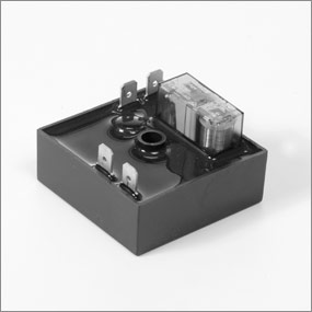
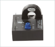
Stetron Sr8cs10dc24 Distributor,Stetron Sr8cs10dc24 Suppliers,Stetron IC( Integrated Circuits) You’re forwarded here since you search our site for Stetron Stetron SR8CS10DC24 Relay, DPDT, 24V Coil – Parts4heating. Read our guide to relays found in vehicle electrical systems.

to activate one or more relays that then complete one or more other circuits and so carry out. As a Stetron distributor, we supply Stetron’s full line of audio products This formula enables Stetron to provide customized audio solutions at standard product. Stetron Sr8cs10dc24 Distributor,Stetron Sr8cs10dc24 Suppliers,Stetron IC( Integrated Circuits) You’re forwarded here since you search our site for Stetron Stetron SR8CS10DC24 Relay, DPDT, 24V Coil – Parts4heating.
Wiring Diagrams
This page demonstrates several simple ways to wire a relay for various applications. Diagrams will show how multiple relays, one relay or another or just one.Disclaimer: * All information on this site (schematron.org) is provided “as is” without any warranty of any kind, either expressed or implied, including but not limited to fitness for a particular use.
Any user assumes the entire risk as to the accuracy and use of this information. Please verify all wire colors and diagrams before applying any information. This is the diagram below to learn all the pin terminals of a Single Pole Double Throw (SPDT) Relay: The 2 COIL terminals is where the voltage is placed in order to energize the coil.
Place the relay’s rated coil voltage on these terminals. The polarity of the voltage does not matter.

A positive and. I added #’s to the pins in the diagram to help describe wiring. Using pins 3 & 4 – when a current flows between those pins it creates a magnetic field that then moves the internal contact.
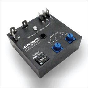
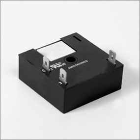
When the relay is unenergized pin #1 is connected to pin #5, this is called Normally Closed (NC). Cube Relay Delayed Interval OFF/ON Timers TGCL Timers TGCL series Cube Relay Delayed Interval (Dual Adjustable) Off/On timers are a unique combination of solid-state timing circuitry with a relay output in a compact cube configuration.
When power is applied to timer input voltage terminals, the timer output relay is energized for the duration of time delay; When the time delay expires, the timer output relay is .Stetron International, Incswitches – Wiring a SPDT Relay – Electrical Engineering Stack Exchange
