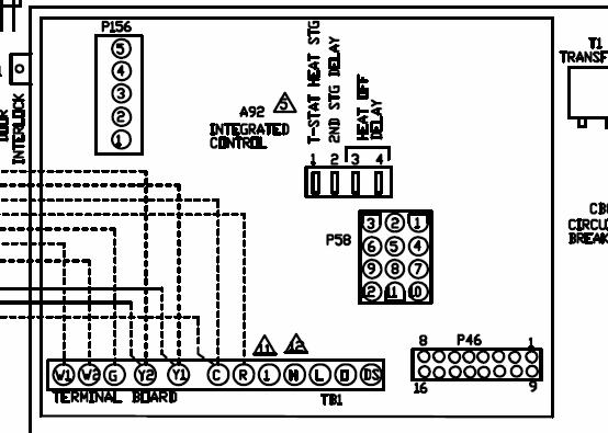
Power Venter or UC1 wiring section for complete details. If replacing an .
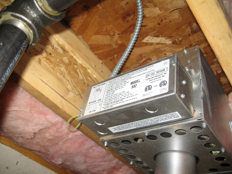
CAUTION: The owner of the SS2 must keep the area around the vent terminal floor joists. Follow same procedure if floor trusses are used, (See Diagram B).
b) If the. Tjernlund Motor Kit for SS2 Sidewall Power Venter call for heat signal that was wired to the blue leads of an old HSUL series power venter would be.
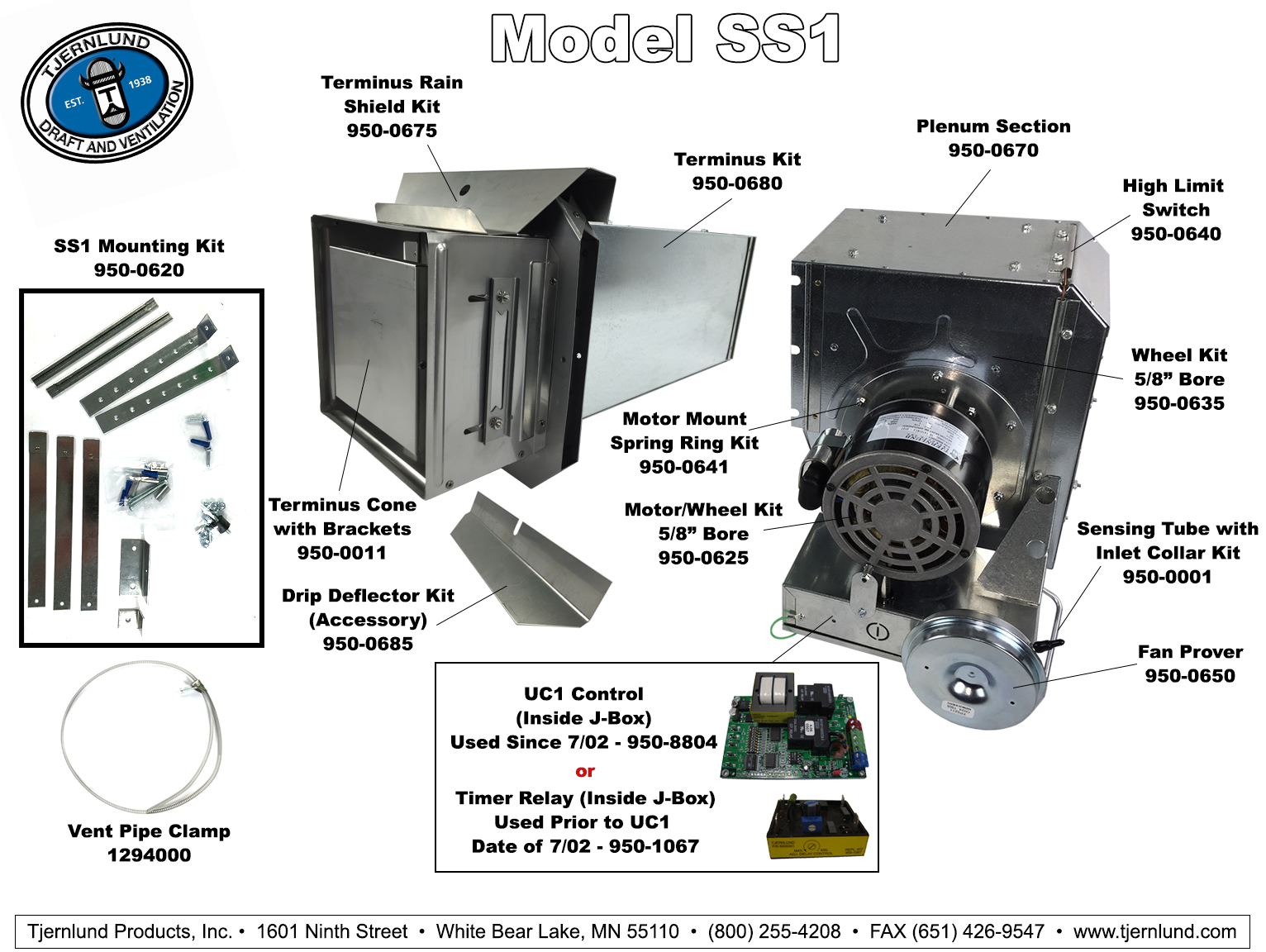
View and Download TJERNLUND SS2 SIDESHOT WITH UC1 UNIVERSAL CONTROL (VERSION LED #3 (Green) Power switched to Venter motor from L to MTR & M. . (See Diagram B). b) If the SS2 is not being installed between floor joists, attach the template Wiring colors or designations may vary by manufacturer.

Tjernlund SS2 Motor Kit Rev. 05/98 User Manual Remove ( 9) screws from rear and bottom of vent cabinet, (See Diagram B). 4.
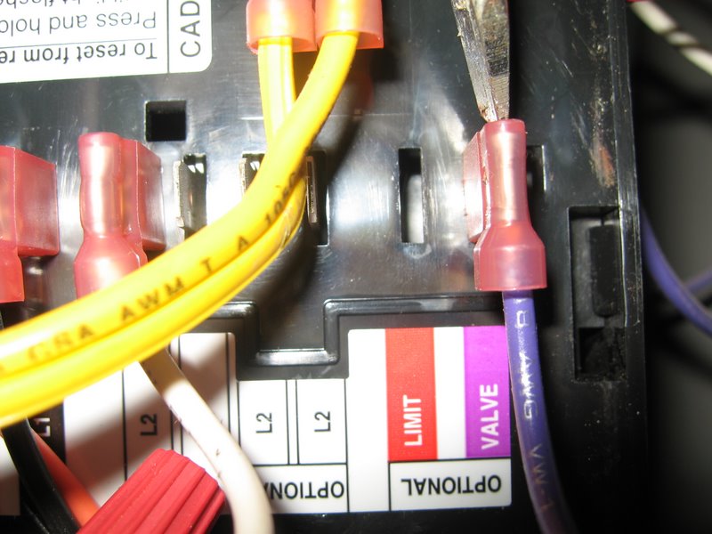
Reconnect supply and control voltage wires disconnected in step 1 and reestablish power. I’ve read plenty about how power venters are, in general, or know anything about how something works to follow Tjernlund’s wiring diagrams.View and Download TJERNLUND SS2 SIDESHOT (DISCONTINUED VERSION-PRE UC1 UNIVERSAL CONTROL) REV B installation instructions manual online.
SS2 SIDESHOT (DISCONTINUED VERSION-PRE UC1 UNIVERSAL CONTROL) REV B Telephone pdf manual download. Jan 14, · In this video I show the installation of a Tjernlund sidewall venter.
http:schematron.org WIRING INSTRUCTIONS Wire the venter motor and controls in accordance with the National Electrical Code, manufacturer’s recommendations and/or applicable local codes. UNIT MUST GROUNDED. Check ground circuit to make certain that the unit has been properly grounded.
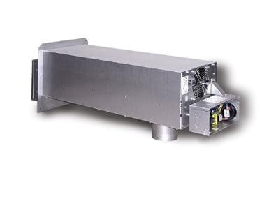
Disconnect power supply from the SS2 and heating equipment when making wiring connections and servicing the SS2. Failure to do so may result in personal injury and/or equipment damage.
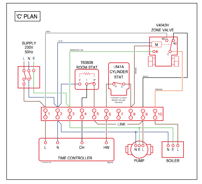
2. Failure to install, maintain and/or operate the SS2 in accordance with manufacturer’s instructions may result in conditions (See Diagram A). The company I work for is having a problem with two of the Tjernlund power venters a HS-2 and a SS They seem to set the burner control on rest.

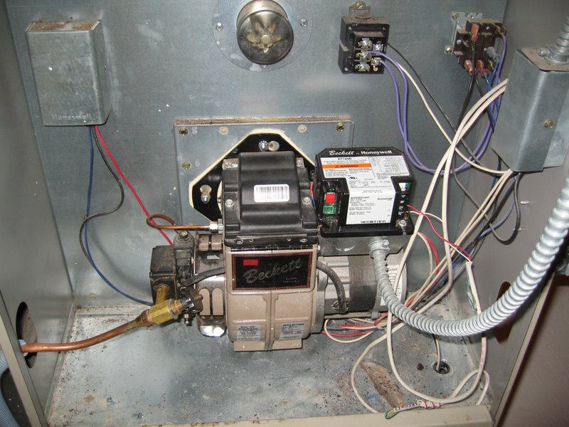
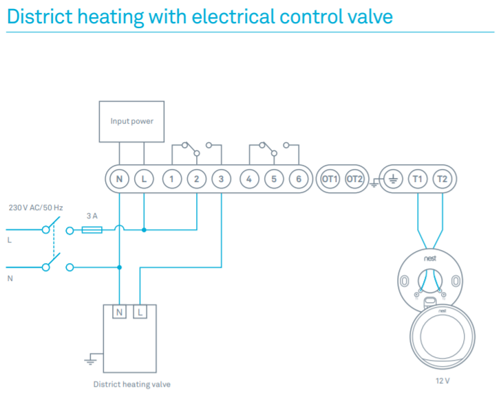
We contacted Tjernlund and they had given us a wiring diagram to isolate the burner from the power venter. Wiring it will tell if the problem is in the power venter or the burner control.Tjernlund SS2 Motor Kit Rev.
05/98 User Manual | 2 pagesFIELD CONTROLS CK MANUAL Pdf Download.