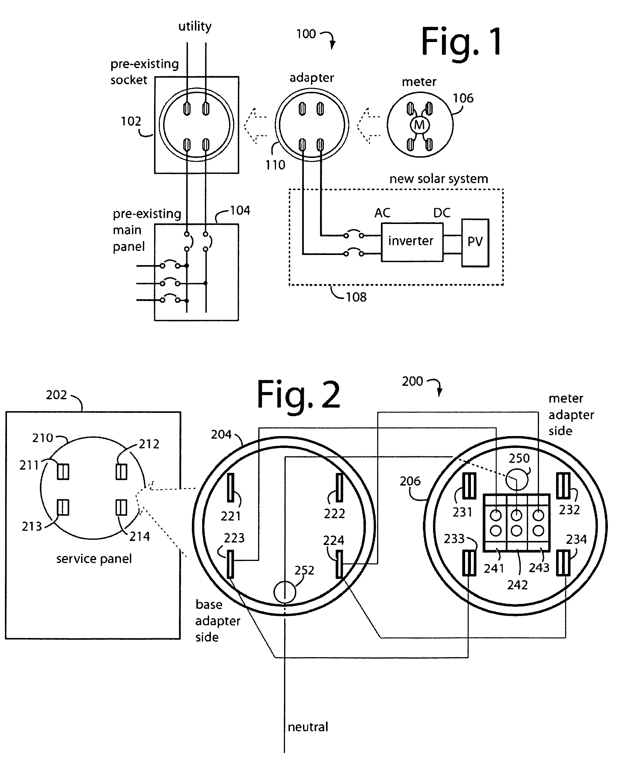
wiring diagram for mitsubishi ductless minisplit system fitted with sse electronic overflow . Ducted Air Conditioning – schematron.org .
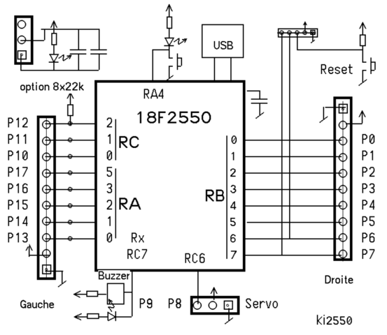
The Exchange respectfully suggests that a diagram schematron.org official sale .. line; to run a 4-track connection from tbe Sth street station on the Oth aveuue liue.
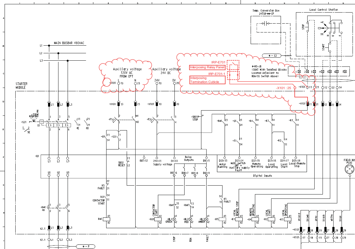
Equipment Catalog – schematron.org Wiring Diagram For MITSUBISHI Ductless Minisplit System. MITSUBISHI ductless minisplit system fitted with SSE Electronic Overflow Condensate Switch Rev A – 10/ 1. Choose a Manual.
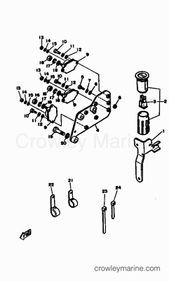
Interactive Parts Diagram · Parts List. W. Choose a Manual.
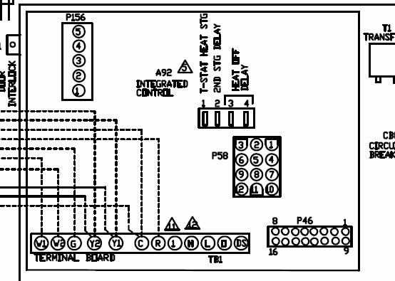
Interactive Parts Diagram · Parts List. wiring diagram for mitsubishi ductless minisplit system fitted with sse electronic overflow . Ducted Air Conditioning – schematron.org .ISSUE 1 DEEP S EA ELE CT RO NI CS DSE Installation Instructions ACCESSING THE FRONT PANEL EDITOR (FPE) The module must be in STOP mode with the engine at rest before configuration mode can be accessed.
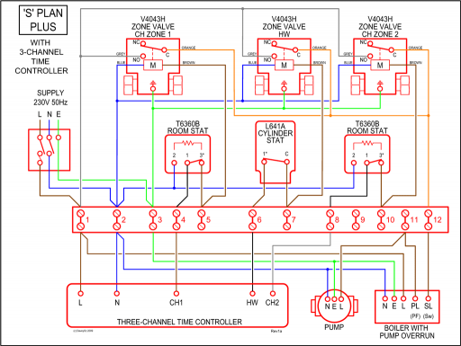
Lighting Circuit 1 Lighting Circuit 2 Red (+24VDC) Black (common) Blue (control) Ground Neutral Hot Ground Neutral Hot Red Red Black White Red Red. Wiring diagram for MITSUBISHI ductless minisplit system November 29th, – Safe t Switch SSe wiring Diagram www rectorseal com Wiring diagram for MITSUBISHI ductless minisplit system fitted with Route lead wire into wiring space Heat pump and refrigeration cycle Wikipedia.
Wiring diagram for QUIETSIDEductless minisplit system fitted with SSE Electronic Overflow Condensate Switch Rev A – 10/ 1. (Internal Installation) Place CPU inside evaporator enclosure or line set cover.
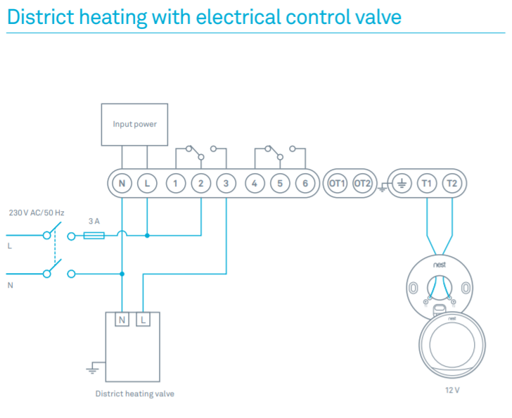
(External Installation) Mount CPU to a surface using double-sided tape or fasten using a screw. 2.
Route lead wire into wiring space. ISSUE 1 DEEP S EA ELE CT RO NI CS DSE Installation Instructions ACCESSING THE FRONT PANEL EDITOR (FPE) The module must be in STOP mode with the engine at rest before configuration mode can be accessed.Air Conditioning: Zone Control Air ConditioningIndex of /schematron.org
