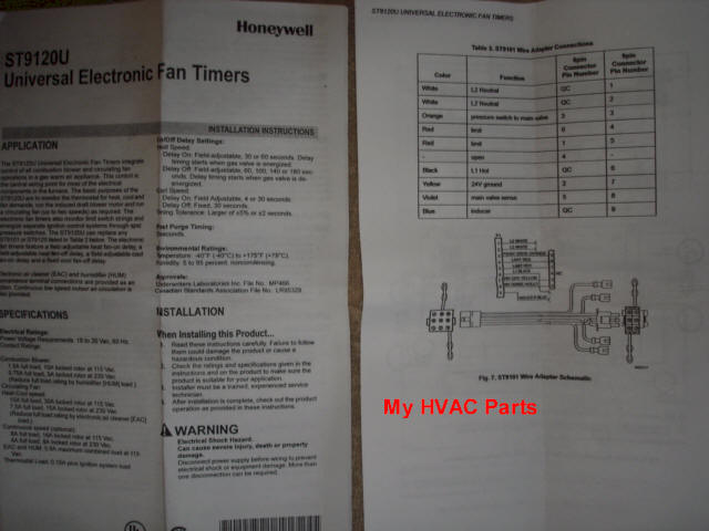
board to a stU? the Honeywell wiring diagram doesn’t address the motor leads for the orignial stC Where do the orange wires go???.
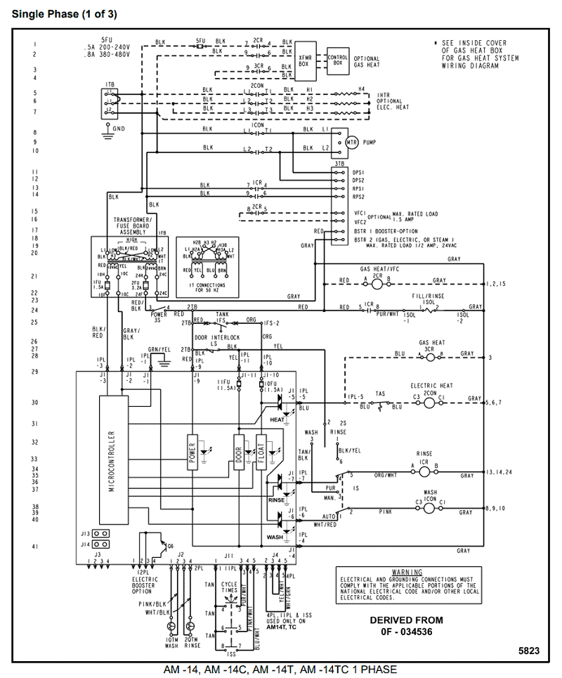
Installation Instructions. FIXED SPEED FURNACE CONTROL.
REPLACEMENT KIT. NOTE: Read the entire instruction manual before starting the. LOOKING FOR A WIRING DIAGRAM TO SWITCH A HONEYWELL stc BOARD TO A hONEYWELL stu – Honeywell Fan.
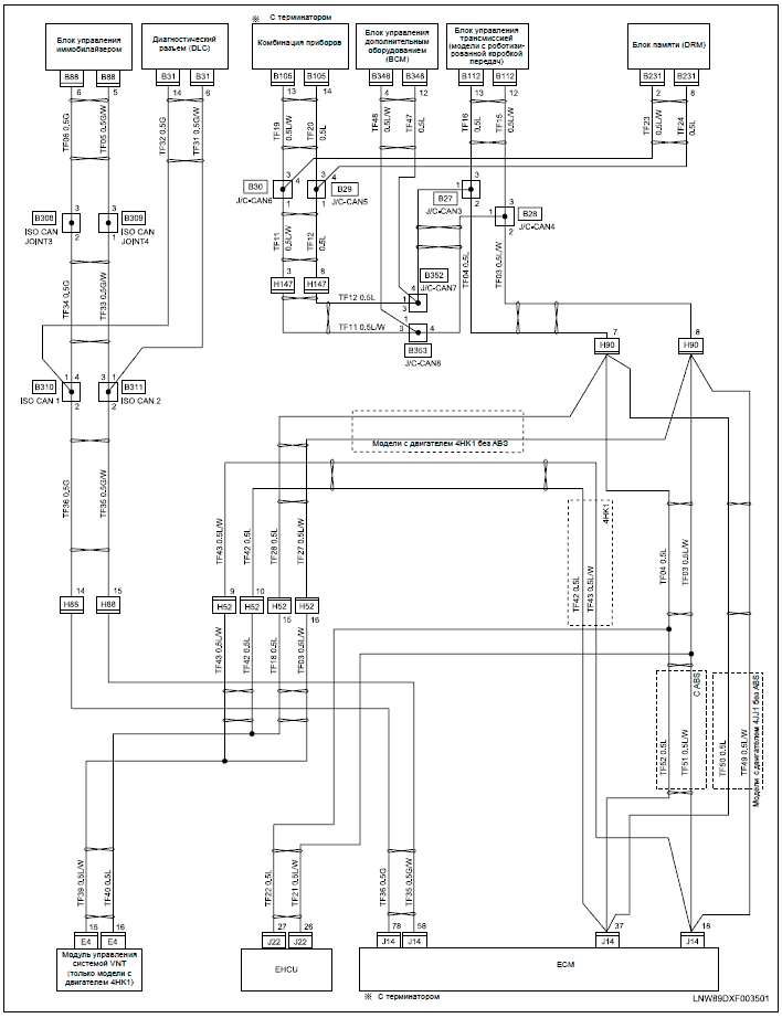
Board Wiring Diagram file PDF Book only if you are registered here. .
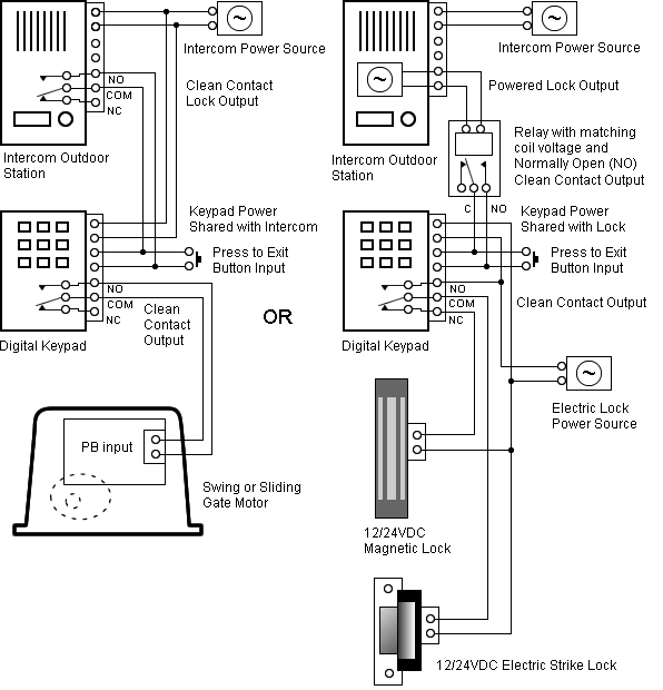
board to a stU the Honeywell wiring diagram doesn t address. Features.
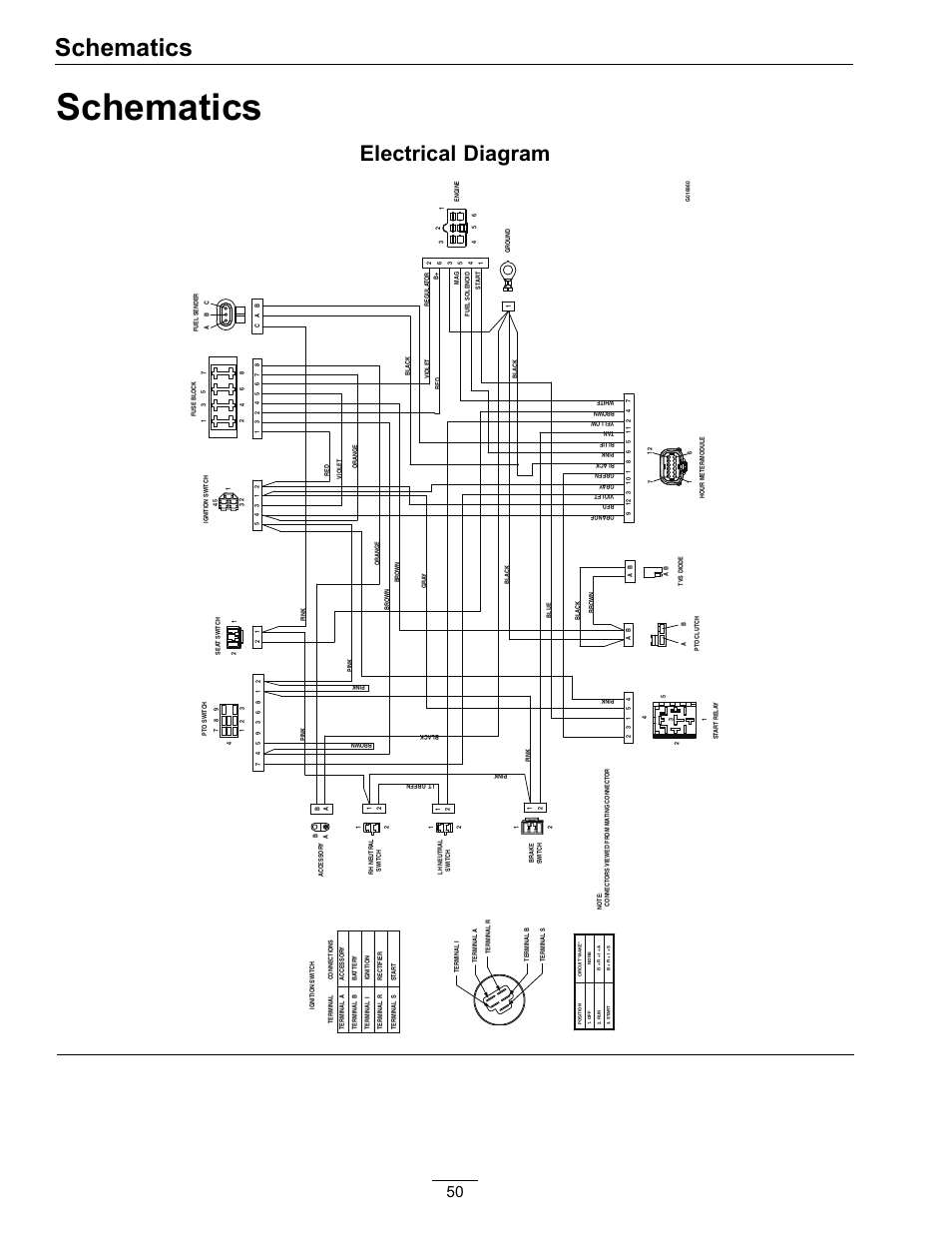
Replaces 40+ existing Honeywell electronic fan timers; Instruction sheet supplies full cross reference and wiring guide; Interface harnesses for simple.The New STU universal platform will not only integrate control of all combustion blower and circulating fan operations in a gas warm air appliance but also replace all . The wiring diagram provided by Honeywell does not address on which terminals the orange wires labeled 22 and 21, these leads went to the motor lead terminals on the original controller.
We need a wire to wire cross-reference for the controllers because we are unable to access their tech support.

Nov 01, · Honeywell STU Universal Control Board Description: Universal Electronic Fan Timer with adjustable heat fan on, heat fan off, cool fan on, and cool fan off. EF STU Universal Electronic Fan Timers APPLICATION The STU Universal Electronic Fan Timers integrate control of all combustion blower and circulating fan operations in a gas warm air appliance.
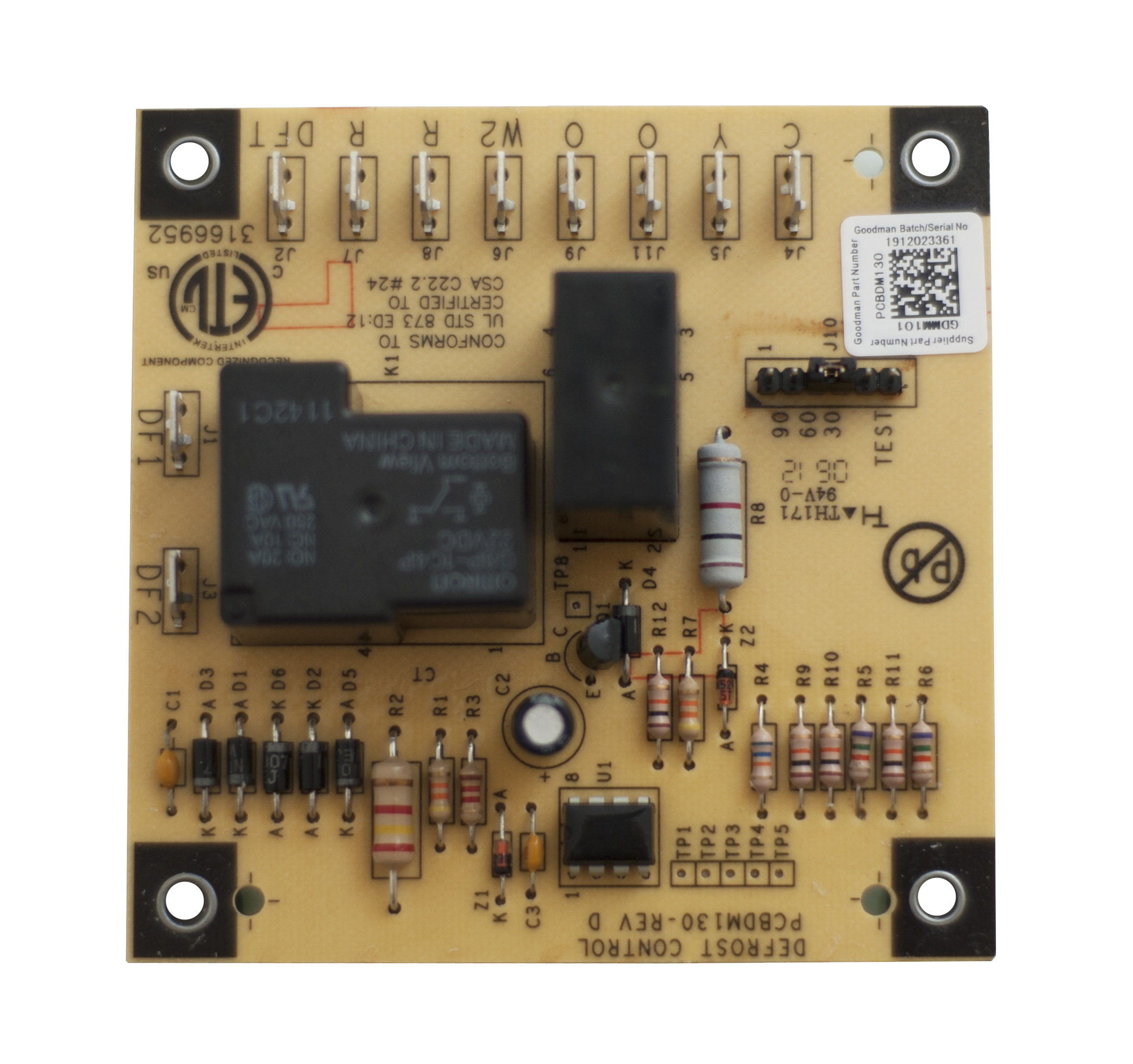
This control is the central wiring point for most of the electrical components in the furnace. The basic purposes of the.
Honeywell STU Universal Electronic Fan Timer old board works great easy to install dip switches new board worked great year old mounting holes straight forward fan control wiring diagram new holes fan timer fan motor universal electronic diagnostic led drilling new easy to follow electronic fan/5().Goodman Control Board B InstructionsSTU Universal Electronic Fan Timer – Honeywell ForwardThinking