Standing Operation through Pilot+ Joystick (Only select VS seats). . ICS Bus Connections. ..
This will be the position that will be stored using the following steps. .
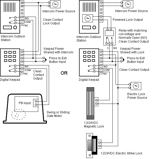
system using a PC based software application created by Permobil. .. This could be caused by a bus communication wire between the. The wiring diagram for battery connection. 2.
WheelchairDriver
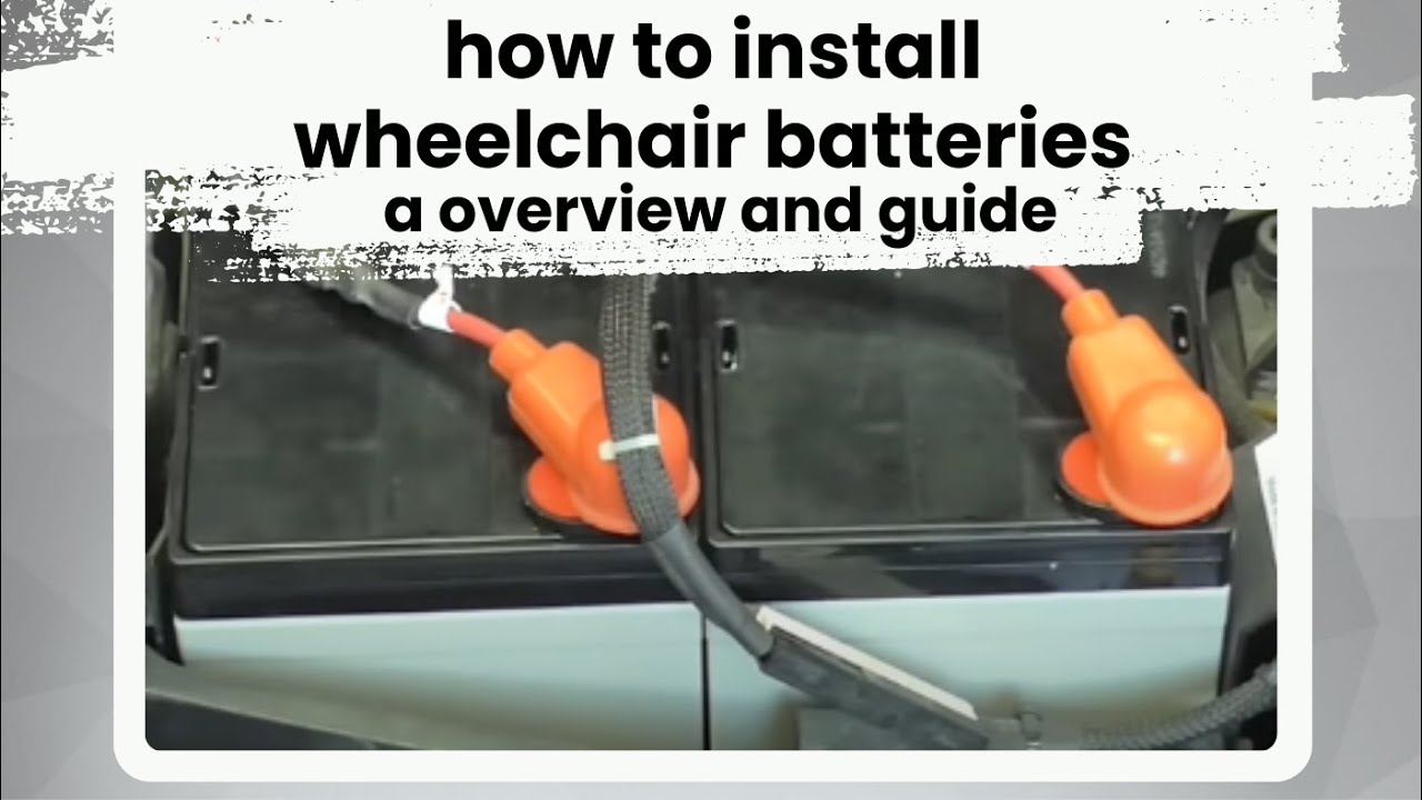
Make sure the batteries are positioned correctly to bring their . Read all instructions carefully before proceeding. If Applies only if the wheelchair is fitted with pneumatic tires. Produced and published by Permobil AB, Sweden.
Edition no.2, .. Screws and nuts must only be used once.
. The electrical connections of the wheel locks are positioned on .. See the diagram of output .. Do not use the wheelchair until the problem has been remedied or you have received other instructions.
Permobil M300 Corpus HD
screws as per diagram. .
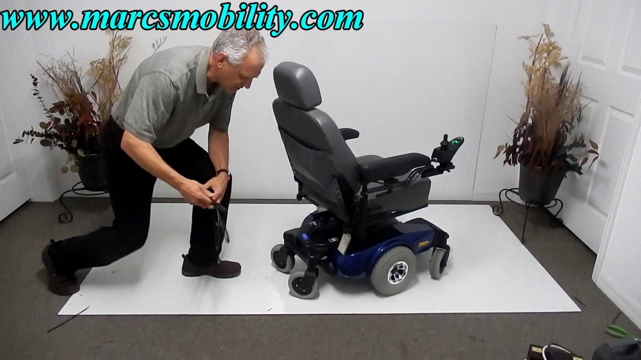
On Permobil M, the batteries are secured with battery locks. .. The spacer is only used on chassis without seat angle mechansim. .
Disconnect the electrical connections from the Power Module. .. the wheelchair until the problem has been remedied or you have received other instructions. Produced and published by Permobil AB, Sweden. Edition no.2, .. Screws and nuts must only be used once.
. The electrical connections of the wheel locks are positioned on .. See the diagram of output .. Do not use the wheelchair until the problem has been remedied or you have received other instructions.Owner’s Manual Permobil M Corpus HD Important Information about this Owner’s Manual Technical support In the event of technical problems, you should contact your dealer or Permobil Inc.
USA at Always state the chassis serial number when contacting Permobil to ensure that the correct information is provided. AMP Research Technical Support.
AMP Research. Mc Gaw. Irvine, Ca wire harness.
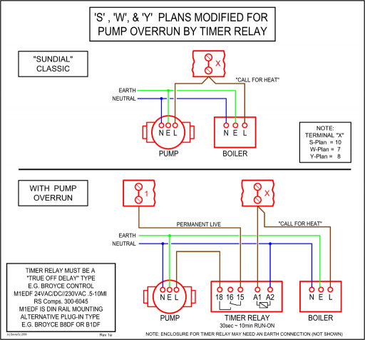
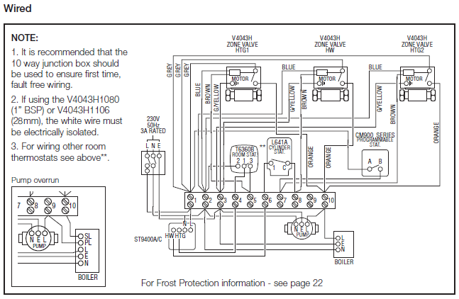
To evaluate the connection between the wire harness and the motor repeatedly open andshut the Complete the balance of the wiring per our wiring diagram. Q: The step only goes up (down) halfway and stops.
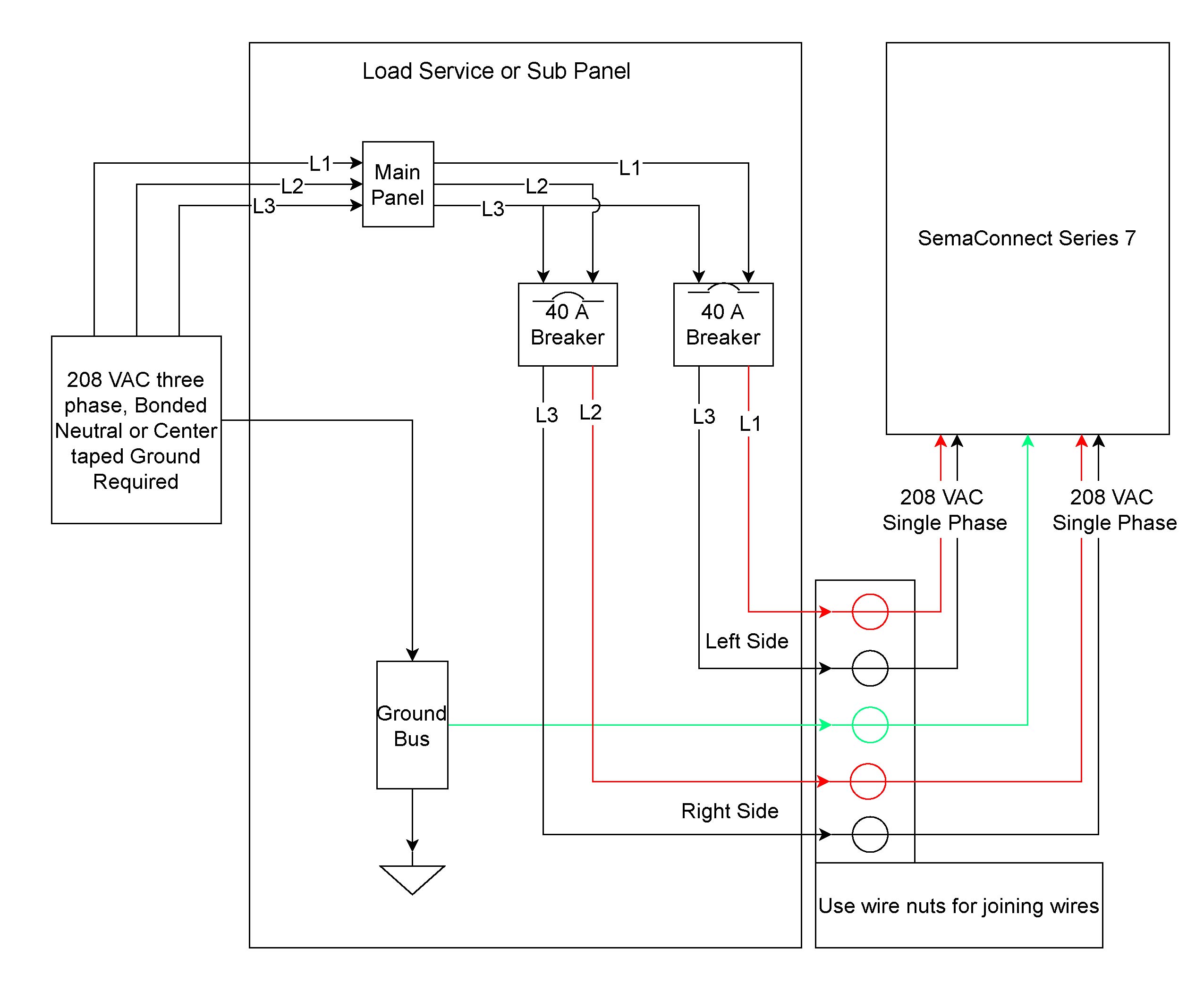
How can I fix it? A: The body of certain. Step 1 Pass the cable through holes Step 2 Mount the Metal Cabinet InBio Pro Series Access Control Panels INSTALLATION GUIDE Power Wiring Diagram Without Backup Battery With Backup Battery Switching Power Supply InBio Pro Series Access Control Panels INSTALLATION GUIDE Lock Connection Normally Open Lock Powered From Lock Terminal. Wiring Diagram shown in this chapter for the step motor lead color code of AutomationDirect supplied motors.) Chapter 4 SureStep™ Advanced Microstepping Drives. Permobil cannot be held responsible for losses of any kind arising as a result of a component of the R-net control system being opened, adjusted or modified without permission.
Page Diagnostics should only be performed by persons with sound knowledge of the wheelchair’s electronic control system.Welcome to PermobilWheelchairDriver • View topic – Changing the Batteries in a Permobil C