
The Strat 3 way switch is one of the most popular pickup switching options for Stratocaster style guitars. It allows you to select between the neck, middle, and bridge pickups, giving you a wide range of tonal possibilities. In this article, we will explore the wiring diagram for a Strat 3 way switch and how it affects the sound of your guitar.
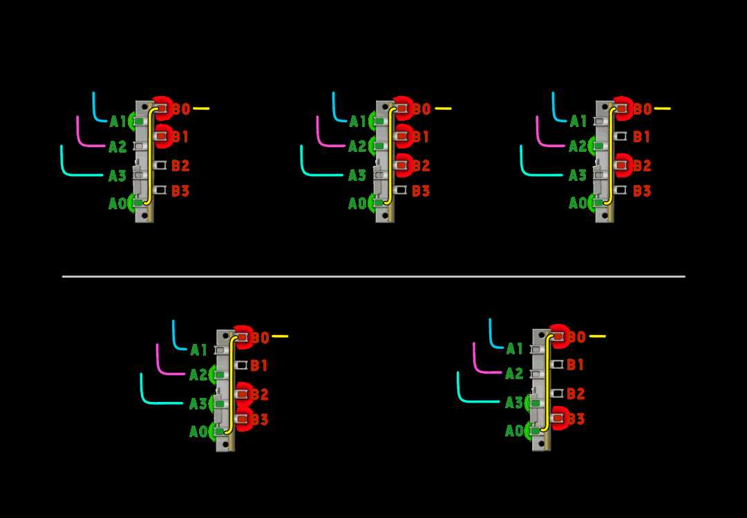
The Strat 3 way switch consists of a lever that is moved up and down to select different pickup combinations. When the switch is in the up position, the neck pickup is engaged. When the switch is in the middle position, both the neck and middle pickups are engaged. And when the switch is in the down position, only the bridge pickup is engaged. This switch design is commonly found on Stratocaster style guitars and is known for its versatility.
The wiring diagram for a Strat 3 way switch is relatively simple. It consists of three pickups, each with a hot wire, a ground wire, and a wire that connects to the switch. The switch has three terminals, one for each pickup. When the switch is in the up position, the terminal for the neck pickup is connected to the output jack. When the switch is in the middle position, both the neck and middle terminal are connected to the output jack. And when the switch is in the down position, only the terminal for the bridge pickup is connected to the output jack.
What is a 3-way switch?
A 3-way switch is a type of electrical switch that is commonly used in residential and commercial buildings. It allows you to control a single electrical fixture, such as a light fixture, from multiple locations. This means you can turn the light on or off from two different switches, rather than just one.
The wiring configuration for a 3-way switch is different from a standard single-pole switch. Instead of having just two terminals, a 3-way switch has three terminals: a common terminal and two traveler terminals. The common terminal is typically connected to the power source, while the traveler terminals are connected to the other switches in the circuit.
To use a 3-way switch, you need at least two switches. One switch will be located at one end of the room, while the other switch will be located at the other end. When one switch is in the up position, and the other switch is in the down position, the light fixture will be off. When both switches are in the up or down position, the light fixture will be on. This allows you to control the light fixture from either location.
In addition to controlling lights, 3-way switches can also be used to control other electrical devices, such as ceiling fans or outlets. The wiring diagram for a 3-way switch can be complex, but it is an essential component of many electrical systems.
Understanding the basics of a 3-way switch
A 3-way switch is a type of electrical switch that allows control of a light or other electrical device from two different locations. It is commonly used in staircases, hallways, and large rooms where multiple switches are needed for convenience. To understand the basics of a 3-way switch, it is important to know its components and how they work together.
The main components of a 3-way switch include the switch itself, the electrical wires, and the light fixture. The switch has three terminals: one common terminal and two traveler terminals. The common terminal is usually colored black, while the traveler terminals are typically brass-colored. The electrical wires connect these terminals to complete the circuit.
When the switch is in the up position, the common terminal is connected to one of the traveler terminals. When the switch is in the down position, the common terminal is connected to the other traveler terminal. The position of the switch determines whether the light or device is on or off. This allows for control of the light or device from both switch locations.
It is important to properly wire a 3-way switch to ensure its correct operation. The wiring diagram for a 3-way switch typically shows the connections between the switch, the travelers, and the light fixture. The diagram may also indicate which terminal is the common terminal. It is important to follow the diagram closely and ensure that the wires are connected to the correct terminals.
Understanding the basics of a 3-way switch is essential for anyone who needs to install or troubleshoot these switches. By knowing how the switch works and how to wire it correctly, you can ensure that your electrical system operates safely and efficiently. Whether you are installing a new switch or replacing an old one, taking the time to understand the basics will help you complete the task effectively.
How to Wire a 3-Way Switch
Wiring a 3-way switch can be a bit confusing, but with the right instructions, it can be done easily. A 3-way switch allows you to control a light or fixture from two different locations. This is often used in larger rooms or staircases where you want to be able to turn the light on or off from either end. To wire a 3-way switch, you will need a few basic tools and materials, including wire strippers, electrical tape, and a screwdriver.
To start, turn off the power to the circuit you will be working on. This is crucial for your safety. Once the power is off, remove the cover plate from the existing switch and unscrew the switch from the electrical box. Carefully disconnect the wires from the old switch, taking note of their positions. You will typically have a black wire (the “common” wire), a red wire (the “traveler” wire), and a white wire (the neutral wire).
Step 1: Connect the green or bare copper wire (the ground wire) to the grounding screw on the switch. This wire is typically connected to the metal electrical box.
Step 2: Connect the white wire (the neutral wire) to the silver screw on the switch.
Step 3: Connect the black wire (the common wire) to the dark-colored screw on the switch. This wire is typically coming from the power source.
Step 4: Connect the red wire (the traveler wire) to the remaining screw on the switch.
Step 5: Once all the wires are connected, carefully tuck them back into the electrical box and screw the switch back into place. Replace the cover plate and turn the power back on.
With the 3-way switch wiring complete, you can now control the light or fixture from both locations. When one switch is in the “on” position, the other switch will be in the “off” position, and vice versa. It’s important to note that if you are replacing an existing switch, the wiring may be different, so always double-check before making any connections. If you are unsure about any part of the process, it’s best to consult a licensed electrician for assistance.
Step-by-step instructions for wiring a 3-way switch
When wiring a 3-way switch, it’s important to follow a specific set of steps to ensure proper installation and functionality. Here is a step-by-step guide to help you with the process:
1. Turn off the power: Before starting any electrical work, make sure to turn off the power to the circuit you will be working on. This can be done by flipping the circuit breaker or removing the appropriate fuse.
2. Identify the wires: Identify the wires that are coming from the power source, the wires going to the light fixture, and the wires connecting the switches. The common wire will be identified by a different color or marking, while the other two wires are typically the same color.
3. Connect the common wire: Take the common wire from the power source and connect it to the common terminal of the first switch. This terminal may be labeled as “COM” or have a different color screw.
4. Connect the traveler wires: Take one of the traveler wires and connect it to the “L1” terminal of the first switch. Take the other traveler wire and connect it to the “L1” terminal of the second switch.
5. Connect the remaining wires: Take the remaining wire from the power source and connect it to the “L2” terminal of the first switch. Take the remaining wire from the light fixture and connect it to the “L2” terminal of the second switch.
6. Install the switches: Using the appropriate screws, install the switches into the electrical box. Make sure they are securely fastened and aligned correctly.
7. Restore power and test: Once all the connections are made and the switches are installed, turn the power back on and test the switches. Make sure the light fixture turns on and off properly from both switches.
Following these step-by-step instructions will help ensure a safe and successful wiring of a 3-way switch. If you are unsure about any step, it’s always recommended to seek the assistance of a qualified electrician.
Common 3-way switch wiring configurations
When it comes to wiring a 3-way switch in a strat guitar, there are several common configurations that are used. These configurations determine how the switches and pickups are connected to each other, allowing for different combinations of pickups to be active at any given time.
One common configuration is the “standard” 3-way switch wiring, which is also known as the “stock” wiring. In this configuration, the middle switch position activates the middle pickup alone, while the other two switch positions activate the neck and bridge pickups respectively. This is the most basic configuration and is often found in many strat-style guitars.
Other wiring configurations

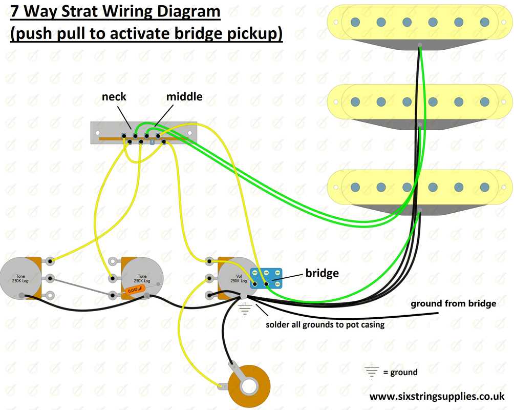
- Neck and bridge pickups in parallel: In this configuration, the middle switch position activates both the neck and bridge pickups in parallel, while the other two positions activate the neck and bridge pickups individually. This configuration can provide a thicker, fuller sound.
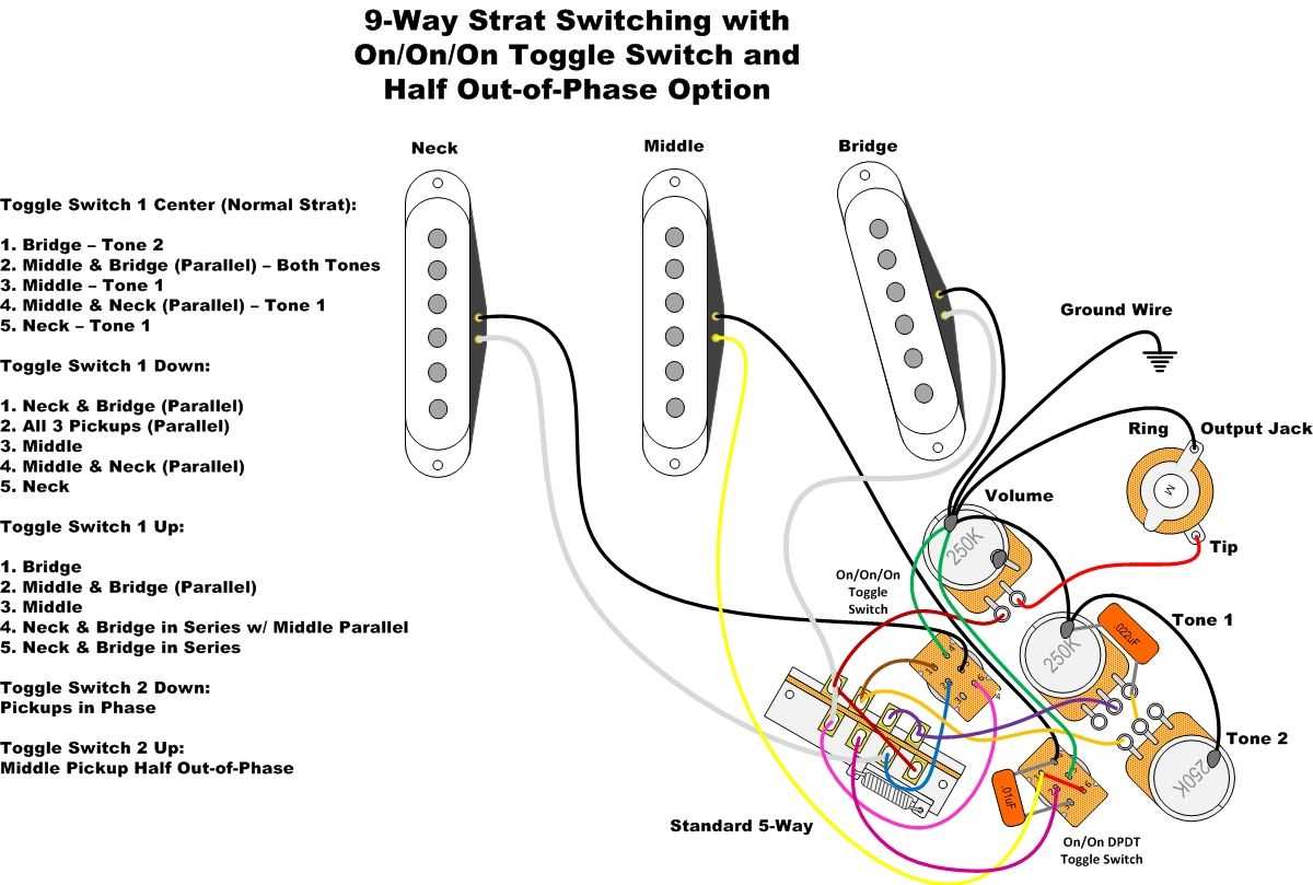
- Neck and bridge pickups in series: This configuration is similar to the parallel wiring, but with the neck and bridge pickups connected in series, rather than in parallel. This can provide a more powerful, higher output sound.
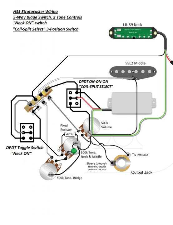
- Coil splitting: This configuration allows for one or more of the pickups to be split into single-coil mode, effectively turning a humbucker pickup into a single-coil pickup. This can provide a wider range of tones and is often used in combination with other wiring configurations.
These are just a few examples of the many possible 3-way switch wiring configurations that can be used in a strat guitar. Each configuration offers its own unique sonic possibilities, allowing guitarists to customize their tone to their liking.
Exploring different ways to wire a 3-way switch
When it comes to wiring a 3-way switch, there are several different methods that can be used. Each method offers its own set of advantages and disadvantages, and it is important to choose the one that best fits your needs. Let’s take a look at some of the different ways to wire a 3-way switch.
1. Traditional “strat-style” wiring: This is the most common and widely-used method for wiring a 3-way switch. It involves connecting the hot wire to the common terminal of one switch, and then connecting the travelers to the corresponding terminals on the other switch. This wiring configuration allows for full control of the light or device being controlled by the switch.
2. Cross-wiring: Another method for wiring a 3-way switch is to cross-wire the travelers. This involves connecting the hot wire to the common terminal of one switch, and then connecting one traveler wire to the common terminal of the other switch. The remaining traveler wires are then connected to the corresponding terminals on the switches. This configuration can be useful in certain situations where wiring constraints may limit the use of traditional wiring methods.
Other possible wiring configurations:
- Switch loop: In this method, the hot wire is connected to the common terminal of one switch, and a traveler wire is used to connect the other switch to the light or device being controlled.
- Dimmer switch: A dimmer switch can also be wired in a 3-way configuration, allowing for control of the light’s brightness from multiple locations.
- Smart switch: With the rise of smart home technology, there are now smart switches available that can be wired in a 3-way configuration. These switches offer additional features such as remote control and voice command capabilities.
When deciding on the best way to wire a 3-way switch, it is important to consider factors such as the layout of the space, the desired functionality, and any specific wiring constraints. It may be beneficial to consult a professional electrician to ensure proper installation and compliance with electrical codes.
Tools and Materials for Wiring a 3-Way Switch
Wiring a 3-way switch requires a few specific tools and materials to ensure the job is done correctly and safely. Here are some essential items you will need for this project:
- Screwdrivers: You’ll need both a flathead and a Phillips screwdriver for removing and installing screws.
- Wire strippers: These tools are essential for removing the insulation from the wires to make proper connections.
- Wire cutters: Used to cut the wires to the appropriate length.
- Voltage tester: It is crucial to have a voltage tester to ensure there is no electrical current flowing through the wires before starting work.
- Electrical tape: Use electrical tape to secure and insulate wire connections.
- Wire nuts: Wire nuts are necessary for connecting and securing the wires together.
- 3-Way switch: Make sure you have the appropriate 3-way switch for your specific wiring setup.
- Electrical wires: You’ll need the appropriate wires, such as 14-gauge or 12-gauge, depending on the electrical load and code requirements.
- Wire connectors: These connectors are used to join wires together securely.
- Optional: A flashlight or headlamp can be helpful for illuminating dark areas during the wiring process.
Having the right tools and materials on hand will make the process of wiring a 3-way switch much easier and ensure the job is done effectively. It’s important to follow proper electrical safety guidelines and consult a professional if you are unsure about any aspect of the wiring process.
Essential tools and materials needed for the wiring process
Before starting the wiring process for a 3-way switch, it is important to gather all the necessary tools and materials to ensure a smooth and successful installation. Here are the essential items you will need:
- Wire stripper: This tool is used to remove the insulation from the wires, allowing for easy connection.
- Voltage tester: A voltage tester is essential for checking the presence or absence of electricity in a circuit. This is crucial for safety reasons.
- Screwdriver: A screwdriver with the appropriate size and type of head is needed for loosening and tightening the terminal screws.
- Wire cutter: A wire cutter is used to cut the wires to the required length.
- Needle-nose pliers: Needle-nose pliers are useful for bending and shaping the wires.
- Electrical tape: Electrical tape is used to insulate the exposed wires and provide added safety.
- Wire nuts: Wire nuts are used to secure and connect wires together.
- Stranded wire: Stranded wire is often used in wiring projects as it is more flexible and easier to work with compared to solid wire.
- 3-way switches: Of course, you will need the 3-way switches themselves. Make sure to choose switches that are suitable for your specific needs and comply with local electrical codes.
Overall, having the right tools and materials will make the wiring process much smoother and ensure a safer installation. It is important to double-check that you have everything you need before getting started. Always follow proper safety procedures and consult a professional electrician if you are unsure about any step of the process.