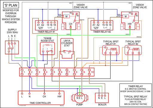
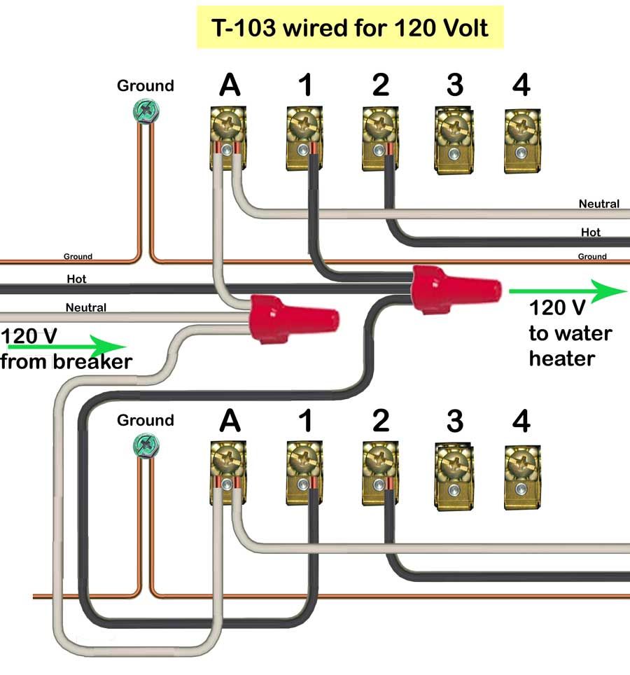
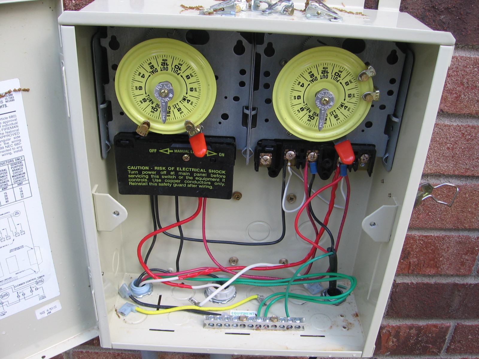
Line in 1 is first hot line 2 in is 2nd hot the load 1 and load2 go to the pump motor on L1 and L2 green is ground to the case.
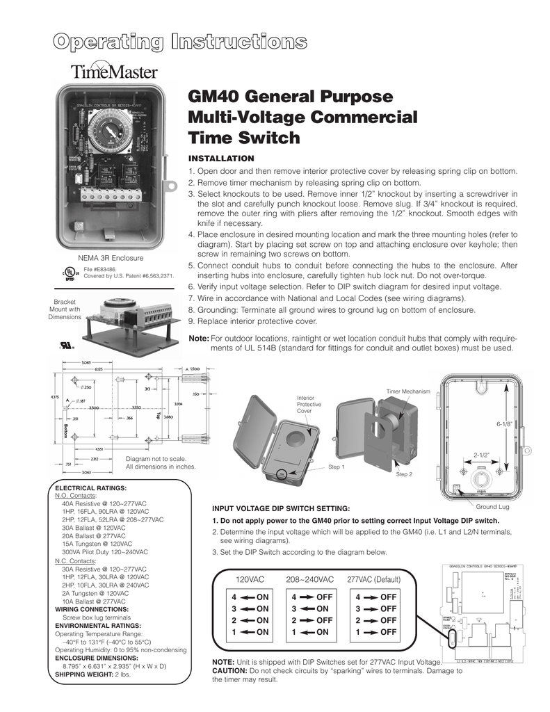
The following steps will provide a guide on how to install the T timer. The T Series Mechanical Time Switch has proven it can stand the test of time. These dependable time switches can handle electrical loads up to 40 A per.

How to operate and set T series timer. T & T are Volt timers; T, T & T are Volt timers.
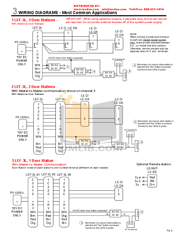
Each timer has different wiring options. WIRING INSTRUCTIONS: To wire switch follow diagram above.
Use solid or stranded COPPER only wire with insulation to suit installation. See gauge selection.Diagrams Specification The time switch shall be a Hour dial type, capable of permitting up to 12 ON/OFF operations each day.
The time switch shall provide a minimum ON/OFF time of 1 hour. The time switch to be powered by VAC, 60 Hz power supply.
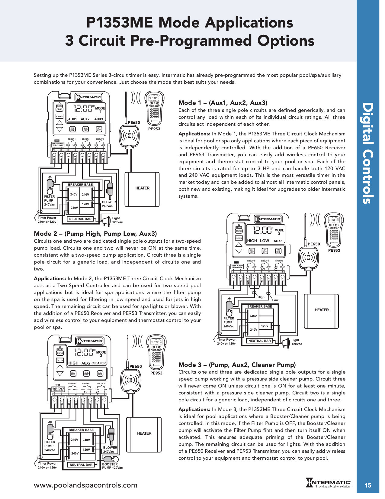
The T Series Mechanical Time Switch has proven it can stand the test of time. These dependable time switches can handle electrical loads up to 40 A per . WIRING INSTRUCTIONS:To wire switch follow diagram above.
Use solid or stranded COPPER only wire with insulation to suit installation. See gauge selection table for normal service applica-tions.
To make power connections remove 1/2 inch of insulation from wire ends. Insert bare ends of wire under the pressure plate of terminals. Wiring Instructions for an Intermatic Timer.
Intermatic Incorporated manufactures timer switches designed for indoor and outdoor use. Many pool pump motors and water heaters use Intermatic timers to regulate their run times.
An Intermatic timer-switch saves electricity when it turns a water heater off at night and when it limits the amount of time. WIRING DIAGRAM V 2 WIRE AND GROUND LR UL HOLOGRAM LABEL WARNING Risk of Fire or Electric Shock • Disconnect power at the circuit breaker(s) or disconnect switch(es) before installing or servicing.
• Installation and/or wiring must be in accordance with national and local electrical code requirements.How to wire Intermatic T and T and T timersSOLVED: How to wire a intermatic timer T v to a – Fixya