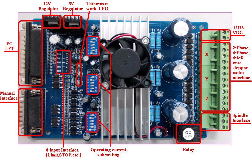
CNC Controller TB A Stepper Motor Driver Board For Mach3. (3 – Axis ) · Datasheet (4 – Axis) · Driver CD · Wiring Diagrams · Stepper Calculator.
1 Introduction; 2 Specification; 3 Pinout Guide and Settings; 4 Setting Method; 5 Wiring Diagram; 6 Sample Code; 7 Test Result; 8 Resources. The 3rd Generation TB Stepper Driver Set.
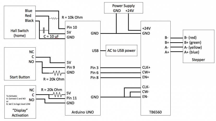
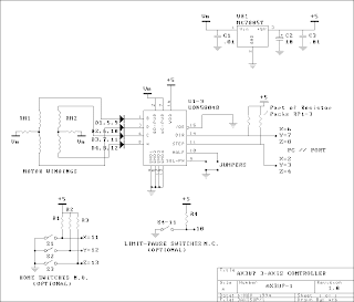
–SAVEBASE . Figure 5: Wiring diagrams for 4/6/8 leads motors. I.
Connections of 4-lead Motors. 4 lead motors. Instead of taking three individual wires from the GRBL/RAMPS board to the TB for the three ground connections (CLK-, CW-, EN-), consider just joining one.
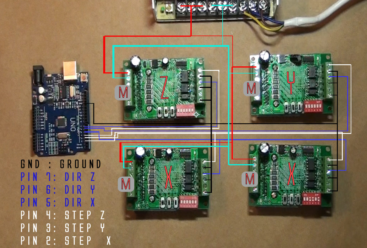
Hello all I am new here and need some help with some basic stuff from you guys. I want to make sure I am hooking up my power supply to the.wire, if this is not possible, note down the colour wire you used to connect to the corresponding wire on the stepper motor (you’ll need to know this when wiring the TB).
Tighten the screws on the rail connector. Run your 4/6 core wire back through your machine and to your enclosure.
This keyestudio board mainly uses the TB stepper motor driver, which is an economical stepper motor driver with high stability, reliability and immunity. It can be applied to various industrial control environments.
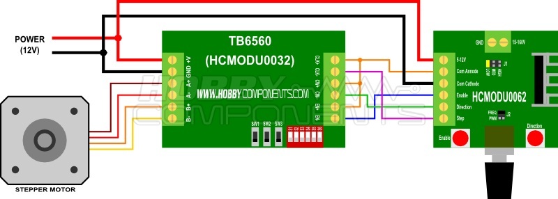
This driver is mainly used to drive Type 35, 39, 42, 57 with 4, 6 and 8-wire two-phase hybrid stepper motors. connected correctly. Incorrect wiring can/will damage the TB driver board.
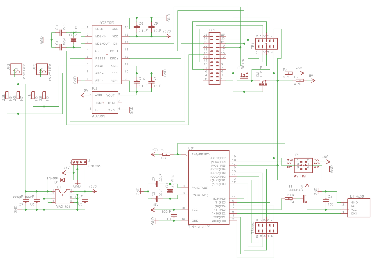
Insert the A+ wire from the Stepper motor in the terminal closest to you, it should line up with pin 12 (XA+) on the TB Now insert the A- wire to the second terminal, it should line up with pin 13 (XA-). UNIVELOP 3-Axis TB CNC Driver Board V Users Manual Univelop Comp.
Tech. LLC.
motor coil diagram of any motor you wish to utilize (making cross connections between 6 WIRE STEPPER DIAGRAM (SERIES WIRING) Center wire of each coil not connected (insulate termination). Jan 27, · TB Wiring Diagram; If this is your first visit, be sure to check out the FAQ by clicking the link above. You may have to register before you can post: click the register link above to proceed.
To start viewing messages, select the forum that you want to visit from the selection below.TB Wiring Diagram