Connecting up to the strip is fairly easy, you’ll want to solder four wires to the white for +12V, then red, green and blue wires for the corresponding LED colors.
This circuit uses the ATtiny 8-pin microcontroller which has 5 I/O pins to create a Since a 7-segment display only requires control of 7 individual LEDs, we use 4 of the Using Sparkfun’s Bluetooth Modem – BlueSMiRF HID to interface between an The following arduino code lets you input two RGB colours and then. Demonstrates the use of PWM pins (analog output) to change the color of an RGB LED.
On Wiring v1 boards the PWM capable pins are: 29, 30, 31, 35, 36 and . Adafruit NeoPixel, Arduino library for controlling single-wire-based LED pixels Adafruit RGB LCD Shield Library, Library for the Adafruit RGB 16×2 LCD Shield.
. ArduinoOSC, OSC library for Arduino (ESP, Teensy, AVR, etc.) SparkFun MetaWatch, A simple library to interface from Arduino to BlueSMiRF to MetaWatch.

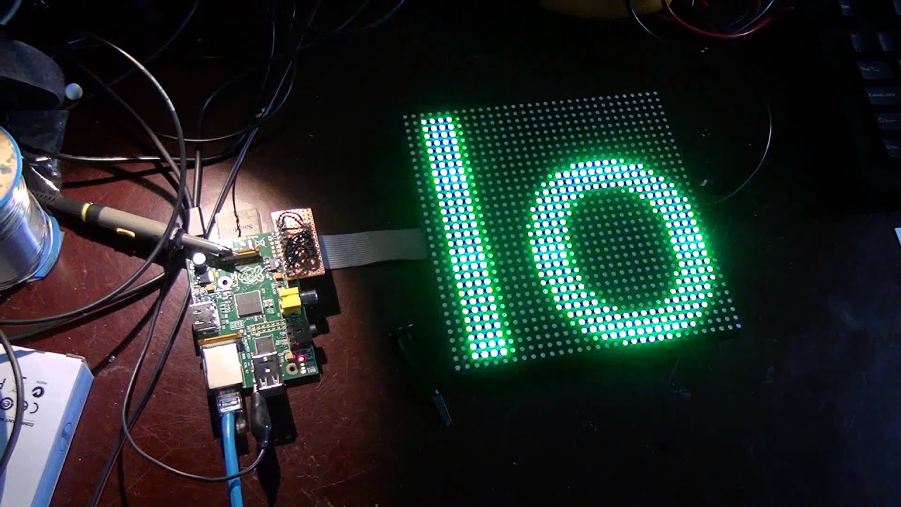
Prototype Wearable LED Dance Harness. February 8 . RGB Panel Hookup Guide .. Getting Started with Electroluminescent (EL) Wire Teensy Arduino Shield Adapter Hookup Guide ..
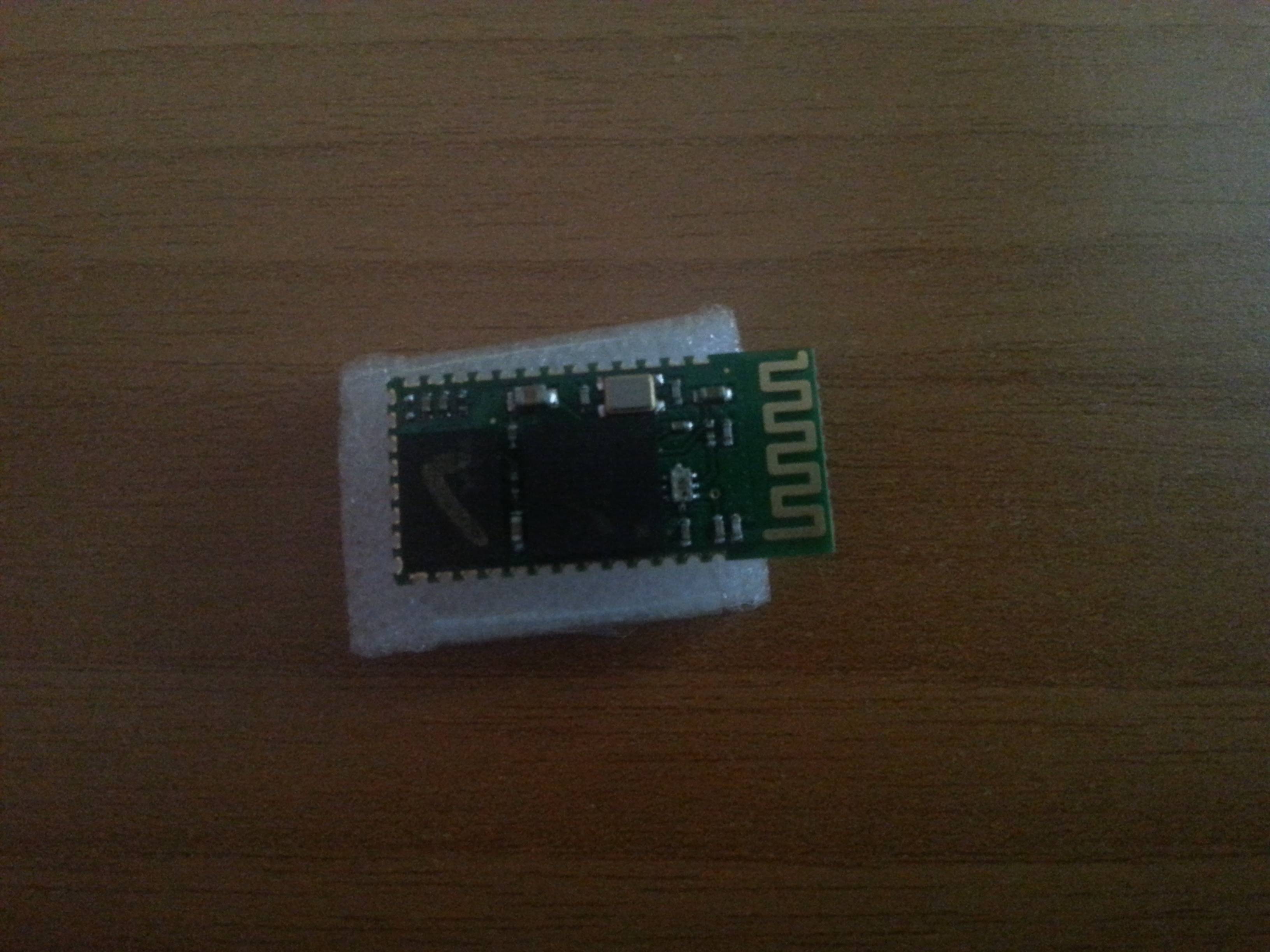
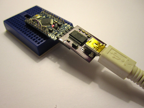
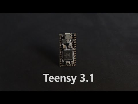
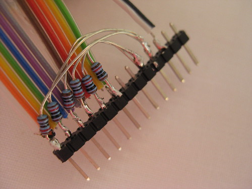
Using the BlueSMiRF Using EAGLE: Schematic.Connect to Teensy Pins With the LED ready, all that’s left is connecting the 3 resistors to 3 pins on the Teensy. There are many pins to choose from! You should pick 3 pins with the PWM feature.
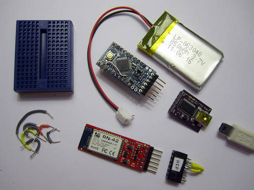
Here are the Teensy pinout diagrams (and the old Teensy diagram). Using the Teensy board, pins 12, 14 and 15 have PWM and are close.
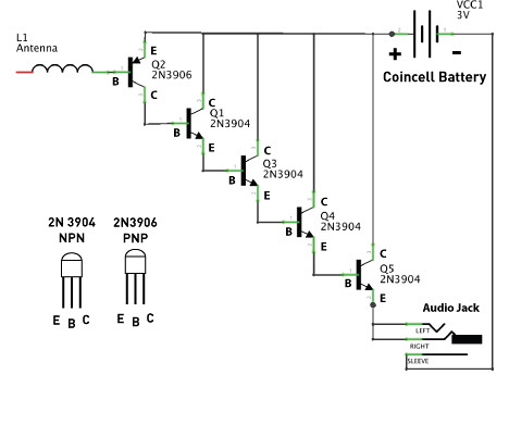
Analog type RGB LED strips come on a reel, and are made of 3-LED sections that are 10 cm long. They are easy to cut at the boundary of each section, theres a little cut mark area and some copper tabs you can solder to. Each LED in a section is a ” tri-color type, containing a red, green and blue LED.
Red, Green, Blue LED with ohm resistors included. This is the same RGB used in the Teensyduino Tutorials.
In this photo, the Green portion is illuminated. The LED is very bright when powered with 5 volts and the ohm resistors. Breadboard and Teensy sold separately.
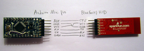
SparkFun is an online retail store that sells the bits and pieces to make your electronics projects possible. Note that this is a Bluetooth Mate shown in the Fritzing diagram, the BlueSMiRF will have a different pinout. TX-O is connected to D2 of the Arduino, RX-I is connected to D3, GND goes to GND, and VCC goes to 5V.
The CTS-I and RTS-O pins are left floating.How To Wire An RGB Colour LED Strip Light With To A Touch Controller (Wiring Diagram)Teensyduino Tutorial #2: Using an RGB (any color) LED