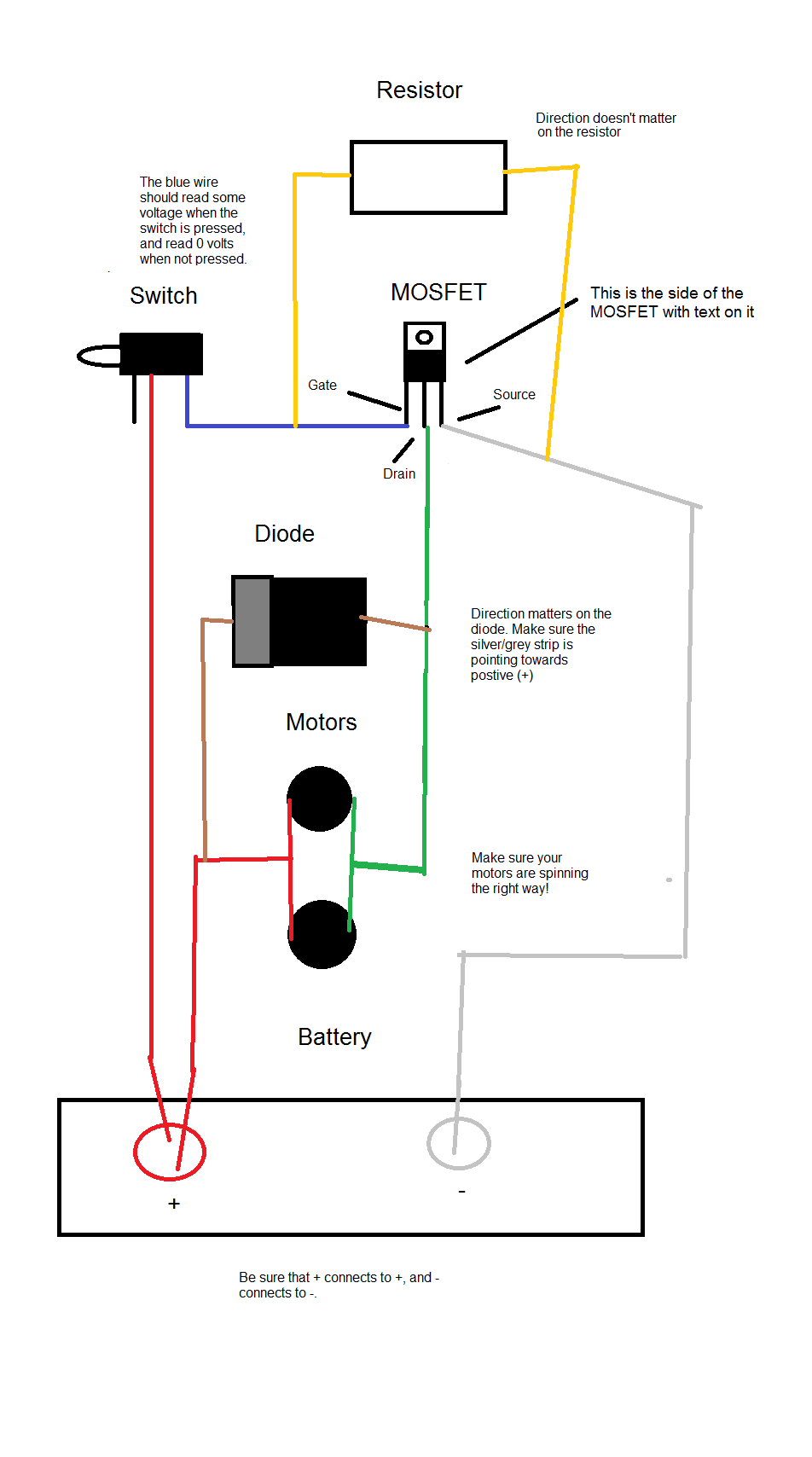
(Coming soon: Pictorial diagrams showing real parts and wiring In the live center circuit, the cycle control switch’s common terminal is.
A complete wiring harness and switch upgrade kit including Blastersmiths UK’s own switch plate upgrade, all the 18AWG wire you’ll ever need and the switches. Rapidstrike select fire circuit diagram – posted in Modifications: Video Then read the state of the pusher switch until it makes a full cycle (Or 3 for burst. Or until trigger is Wait wait wait this would allow for 3 round bursts?.
If you use leaded anywhere, do not use it on the motor or switch terminals. .
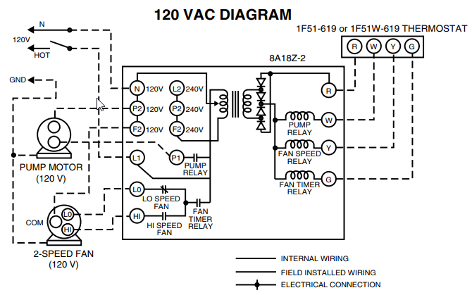
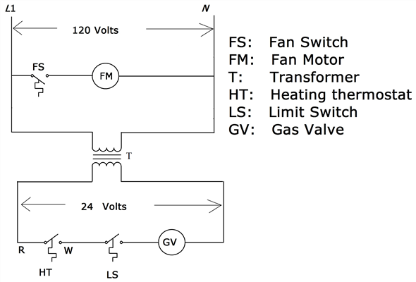
In ” front wiring”, the battery leads exit the rest of the harness at the. Three switch Rapidstrike Wiring Guide, Please let me know if this So I am just now starting my first rapid strike rewire and I wanted to share my wiring plans, let me Not very helpful I know, but that is a really nice diagram!.Option 3.
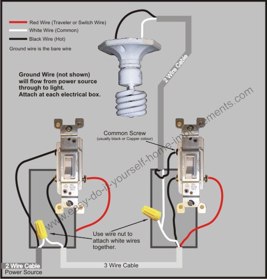
Fixture Between Two Three-Way Switches: Power Through Switch Light is controlled by two three-way switches with the light between the switches and the power first going through a switch, then to the light, and onto the second three-way switch. The ground wire is pigtailed with a wire connector at the switch boxes and the ceiling box. Yes, and the switch you want is VC6.
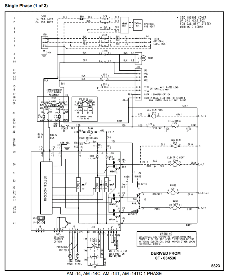
So what wiring diagram do you suggest?? Live center for 12rps or less. Dead center for higher ROF.
You also are saying, unless you are using a wolverine as a pusher that you can use smaller switches for the main trigger switch and cycle control switch right? Yes, and Omron SSGL is my recommendation.
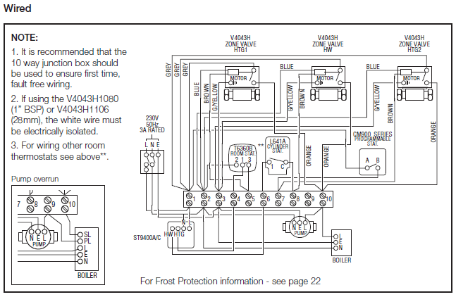
Rapidstrike CS Circuit Schematics. NOTE: These are preserved here for posterity, there are a couple of errors that are to be corrected in a later post.:) The suggested rewire needs electrical braking adding and the motor stack on the flywheels needs completing.
So Steve made these up based on our observations these last couple of days. Because the electrical code as of the NEC update requires a neutral wire in most new switch boxes, a 3-wire cable runs between the light and switch.
The red and black are used for hot and the white neutral wire at the switch box allows for powering a remote controlled switch. (Coming soon: Pictorial diagrams showing real parts and wiring connections) I have had some requests for improved and more complete circuit diagrams as of late. In this post I will cover some of the basic electromechanical Rapidstrike circuits and their applications, behaviors and issues, as well as some general Rapidstrike teching advice.The Dart Zone: Tech: Rapidstrike Control Circuits Part 13 Way Switch Wiring Diagram
