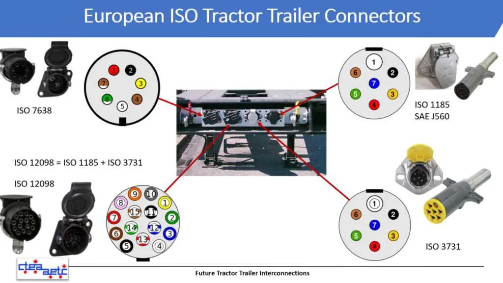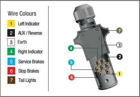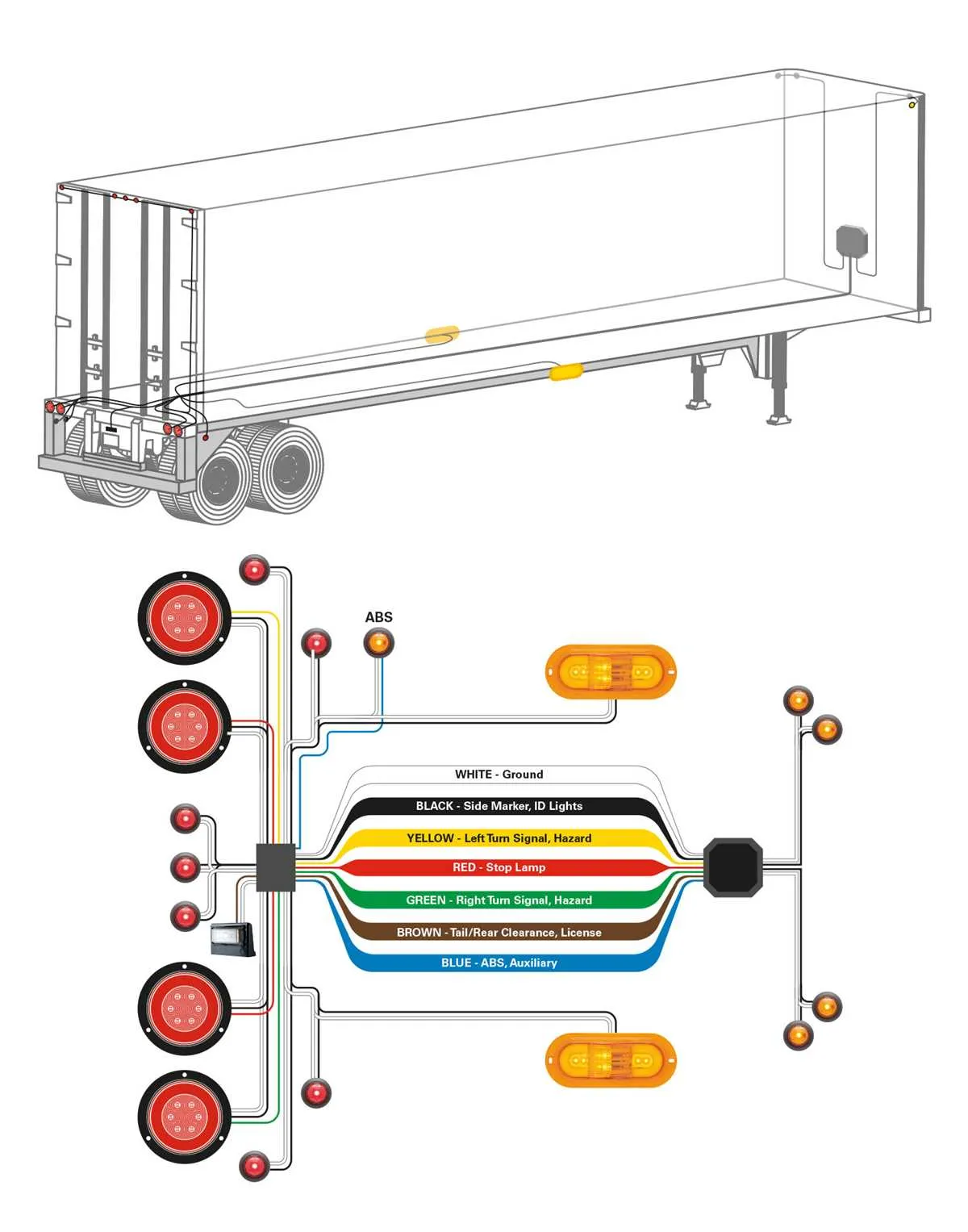
For proper functionality of heavy-duty vehicle connections, ensure all cables are securely attached to their corresponding terminals. Always check that the power, ground, and signal lines are clearly marked and correctly aligned with the input/output pins.
Red wire typically serves the function of the main power supply, carrying voltage from the vehicle’s system to the attached equipment. Ensure this connection is stable to prevent power interruptions during operation.
White wire is responsible for grounding. A firm connection here is crucial to avoid short circuits and other electrical failures. Without proper grounding, the risk of system malfunctions significantly increases.
Green wire is often used for rear lighting signals. Double-check that this line is not obstructed or damaged, as malfunctioning rear lights can lead to safety hazards, especially when driving in low visibility conditions.
Verify that all components, including the connection points and junctions, are free from corrosion or physical damage. A damaged connector can lead to faulty operation, reducing the efficiency and safety of the vehicle.
Connector Pinout and Electrical Configuration

To ensure proper functionality of the vehicle-to-cargo unit connection, follow these key guidelines:
- Use the standard 7-pin setup for heavy-duty connections, which covers all essential signals for lighting, braking, and power supply.
- Ensure that the ground pin is securely connected to prevent electrical faults. It’s crucial for the stability of all connected systems.
- Pin 1 (usually for the left turn signal) should be wired to the vehicle’s corresponding indicator system to enable safe lane changes.
- Pin 2 is typically reserved for the right turn signal, ensuring clear communication with surrounding vehicles.
- Pin 3 often handles the brake lights. Ensure this pin is wired correctly to signal braking action effectively.
- Pin 4 is responsible for the tail light circuit. Check the voltage level to ensure adequate lighting for night operation.
- For the auxiliary power, Pin 5 should be used to power additional systems like refrigeration or other tools on the connected unit.
- Pin 6 is frequently allocated for backup lights or other optional signals, but verify compatibility based on your vehicle configuration.
- Pin 7 can carry an additional feature, often used for electric brake control or other operational needs.
Always use color-coded cables to avoid confusion and ensure that each pin is connected to the correct system. Incorrect wiring can lead to electrical failure or safety hazards during operation.
Test the system after installation to confirm that all signals are transmitted clearly and correctly. Using a test lamp or multi-meter can help identify potential issues with specific circuits.
Understanding the 7-Pin Layout

The 7-pin connector is commonly used for heavy-duty vehicle connections, offering a wide range of functions. Each pin serves a specific role, and understanding its layout is crucial for proper setup. Below is the typical arrangement for a standard 7-pin configuration:
Pin 1: Ground – Provides a return path for electrical current, ensuring proper operation of all systems.
Pin 2: Left turn signal – Controls the left turn indicators, signaling when a left turn is made.
Pin 3: Right turn signal – Powers the right turn indicators, activating the right turn signal lights.
Pin 4: Brake lights – Activates the brake light system, signaling when the vehicle’s brakes are engaged.
Pin 5: Reverse lights – Turns on the reverse lights, aiding in visibility when reversing the vehicle.
Pin 6: Electric brakes – Provides power to the electric braking system, allowing for synchronized braking between vehicles.
Pin 7: Auxiliary power – Supplies extra power for additional accessories like lights or a battery charging system.
Ensure that each pin is connected correctly according to this standard layout to maintain the functionality of the system and prevent malfunctions.
Common Electrical Issues and Fixes
Check for corrosion on the connections. Clean terminals using a wire brush and apply dielectric grease to prevent future build-up. This prevents intermittent contact and reduces the risk of electrical failure.
If you experience flickering lights, inspect the ground connections. A poor ground can cause inconsistent voltage. Tighten or replace ground bolts and clean any rust or dirt buildup around contact points.
For signal failures, verify continuity in the conductors. Broken wires can cause power loss to specific functions. Use a multimeter to trace and repair any breaks, ensuring a secure and clean connection at both ends.
If the connectors are loose, replace them with new ones. Ensure they fit snugly and securely, preventing any slack that can lead to shorts or loss of current flow.
In cases of inconsistent braking lights, check the circuit for a faulty relay or fuse. If the relay does not activate properly, replace it. Always use fuses of the correct amperage rating to prevent damage to the system.
For systems with malfunctioning indicators, inspect the signal wires for short circuits or grounding issues. Resolve any shorts by repairing the wire or replacing damaged insulation to restore proper function.
Testing Your Connections
Start by turning off your vehicle’s ignition. Use a multimeter to check for voltage at each terminal of the connector. Set the multimeter to DC voltage and ensure each pin corresponds to the correct signal output.
For the ground pin, verify continuity with the chassis of the vehicle. A lack of continuity here suggests a broken or faulty connection.
Next, inspect each wire for visible damage or corrosion. Test all active pins for proper voltage output while engaging the corresponding functions (brake lights, turn signals, etc.).
Pay attention to any intermittent readings or fluctuations in voltage, which indicate poor connections or possible short circuits in the system.
Once each function has been tested, reassemble the connection points and apply a protective sealant to prevent moisture or corrosion from compromising the contacts.
Lastly, confirm all signals are properly functioning by activating the respective vehicle controls (lights, brakes, etc.) while monitoring the multimeter for stable readings.