Aux1. Hum.

Hum. BK PWM.
Fan. G.

Relay Panel. 1/8” for screws into studs.

3/16” for drywall information. (See the Field Wiring Diagrams section for com-.
NOTE: This unit as shipped is ONLY compatible with Trane and American IMPORTANT: The TAM8 air handlers are only compat- ible with . 1.
Remove both Heater and Coil panels. 2.
Turn screws on Line Set Panel. 2.
Pull panel . Use a manual driver to avoid stripping .
STEP 2 – Install an auxiliary drain pan under the. ized plug connections on coil EEV Electric Heater, 5kW, Breaker, RS Control, 1 Ph . handler model and the auxiliary heater model n TAM8 AIR HANDLER AND HEATER MATRIX – ALLOWABLE COMBINATIONS.

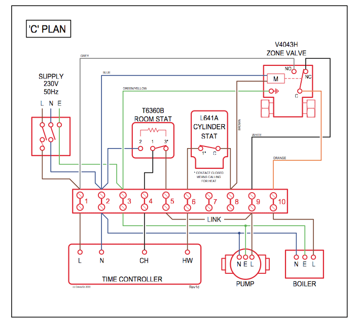
ALL phases of this installation must comply with NATIONAL, STATE AND LOCAL CODES. IMPORTANT . See the Field Wiring Diagrams for Communicating Indoor (excluding TAM8) with Non-Communicating Single Stage Cooling .
Yes, No. Ventilation – Select Relay Panel Aux Contacts .
Aux 1. Aux 2.
Aux1. Hum. Hum. BK PWM.
Fan. G. Relay Panel. 1/8” for screws into studs.
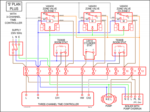
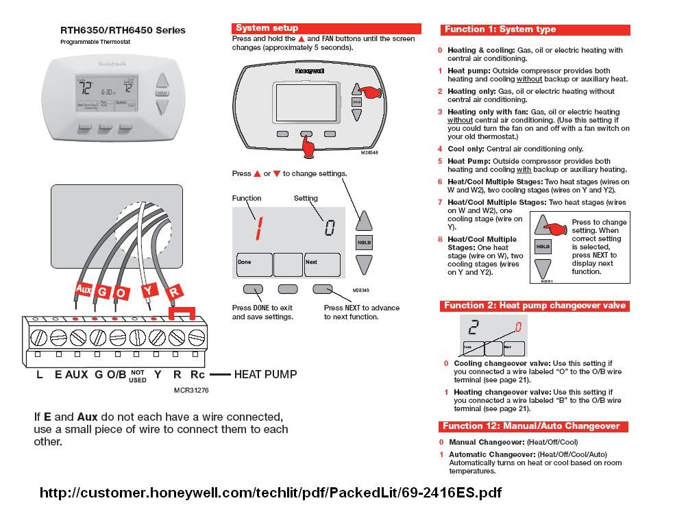
3/16” for drywall information. (See the Field Wiring Diagrams section for com-.Trane Heat Pump Thermostat Wiring Diagram – Gooddy, size: x px, source: schematron.org Whatever you are, we attempt to bring the web content that matches just what you are seeking. 1 – Connector Cable 1 – Wiring Diagram Label Installation 1.

Shut off all power to unit. Observe the caution: OPEN and LOCK the unit’s power disconnect switch to prevent injury of death from electrocution or from contact with moving parts before attempting any installation or maintenance. 2.

Remove unit control box access panel. Variable Speed Modular Multi-position Communicating Air Handlers Tons TAM8A0A24V21CB TAM8A0B30V21CB TAM8A0C36V31CB TAM8A0C42V31CB Field Wiring 19 Convertibility 20 Dimensions 4 Pub.
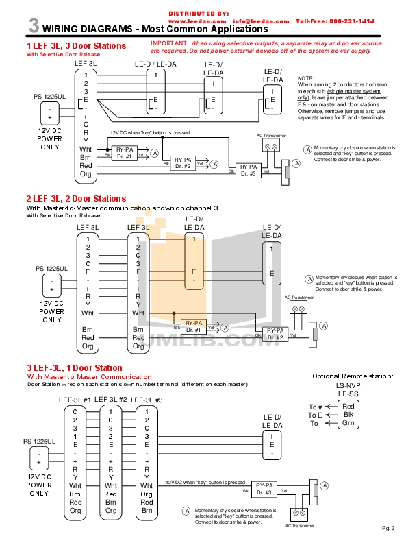
No. Minimum auxiliary heating airflow is automatically configured by the air handler model and the auxiliary heater model number.
This is. WIRING DIAGRAM MANUAL CHARGING (HIGH STAGE ONLY) IN COOLING BETWEEN 55°F AND °F OD AMBIENT Trane recommends installing Trane approved matched indoor and outdoor systems.
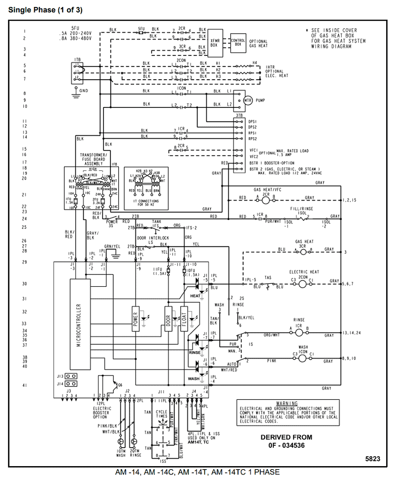
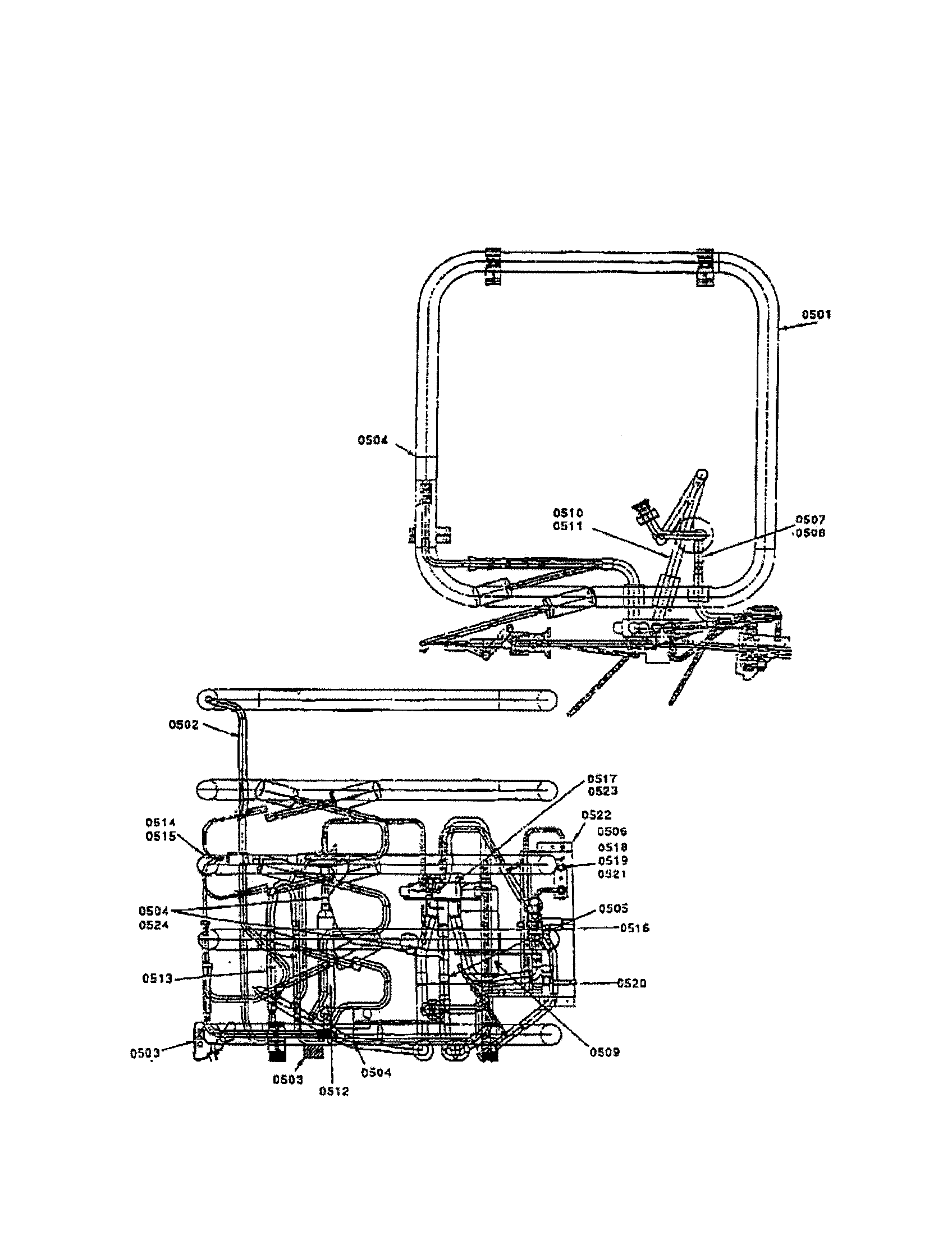
All Trane split systems are AHRI rated with only TXV indoor systems. The benefits of installing approved indoor and outdoor split systems are maximum. © Trane AM8-SF-1J SAFETY SECTION AIR HANDLERS Important — This document contains a wiring diagram, a parts list, and service information.

This is customer property and is to remain with this unit. Please return to See unit, auxiliary heat, and field wiring diagrams .Downflow Furnace Models *FD14DCLFRD *FD17DCLFRD *FD21DCLFRD *FD24DCLFRD – PDFUltimate Guide to HVAC Systems | Trane® HVAC | Owners Support
