
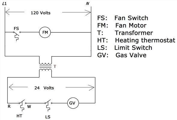
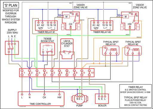
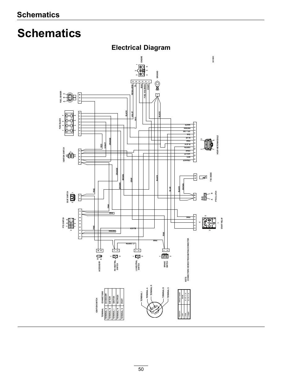
I used that diagram of Rick’s as a starting point, and then traced every single wire by hand. Note this shows the electrical mods that I installed: 1.
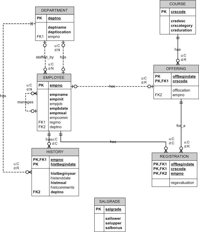
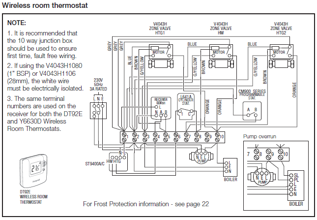
For detailed explanation, see section of the TriMetric TM .. using the chart above and/or wiring diagram (Figure 2) to determine which wire goes to. Installation Diagram Inside the Trimetric, there are 5 hookup jacks for the shunt wiring.
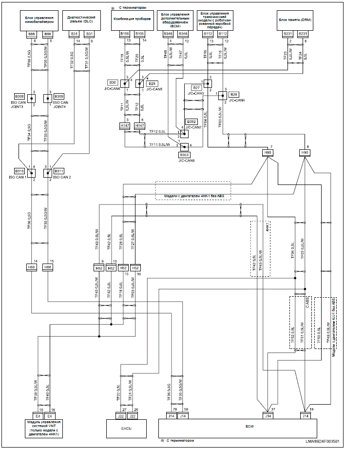
I don’t have. Trimetric signal and data wires hook up.
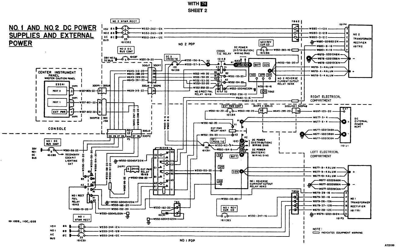
Wiring problem with my Trimetric battery monitor. Without a connection diagram and leading you through specific troubleshooting steps. Connect your TriMetric battery meter to manufacturer’s specs with this 50 foot cable and fuse set.
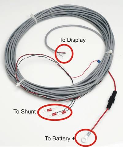
Includes wiring diagram. It has four, #22 AWG gauge wires ( two.Dec 08, · Wiring Diagrams for bat bank, trimetric and solar upgrades Post by Mgittrich» Sun Apr 27, am UPDATED MAY 16 TO CORRECT A MINOR ERROR IN THE PHASE 2 AND 3 WIRING DIAGRAMS. We found the wiring diagram for the Trimetric to be rather confusing, so we later drew our own version of it to hopefully be a bit clearer than the one with the instructions: Step 1.
Find a place near the battery to install the shunt. Trimetric TMRV Deep Cycle Battery Monitor.
NOTE: This is only the monitor and is not a complete system. If you need all the individual parts that make up a complete system, including a charge controller, please see the BMS-TM-RV kit or the BMS-TM-RV kit.
At a minimum, you will need a cable assembly and a A or A shunt to use the battery monitor. STEP 2: Study the wiring diagram on last page of manual.
STEP 3: Install according to section B: METER INSTALLATION. (B) ENTER DATA: To get the TriMetric working the first time, particularly the “Battery % Full” and “Amp-Hours from full”, you need to enter some system data.
For “Battery % Full” to work properly, data in Step 2, Step 3 Step. Posted By: CA Traveler on 05/28/14 pm You should have 3 fuses in the combiner box. The Trimetric requires 4 wires and 5 if you have the and add the chassis battery.
The batteries should be wired in a balanced configuration.Red Rover Trimetric InstallationManuals – Bogart Engineering