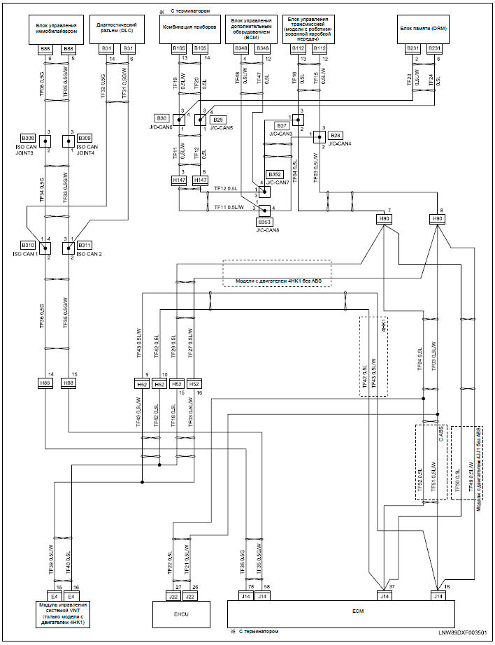
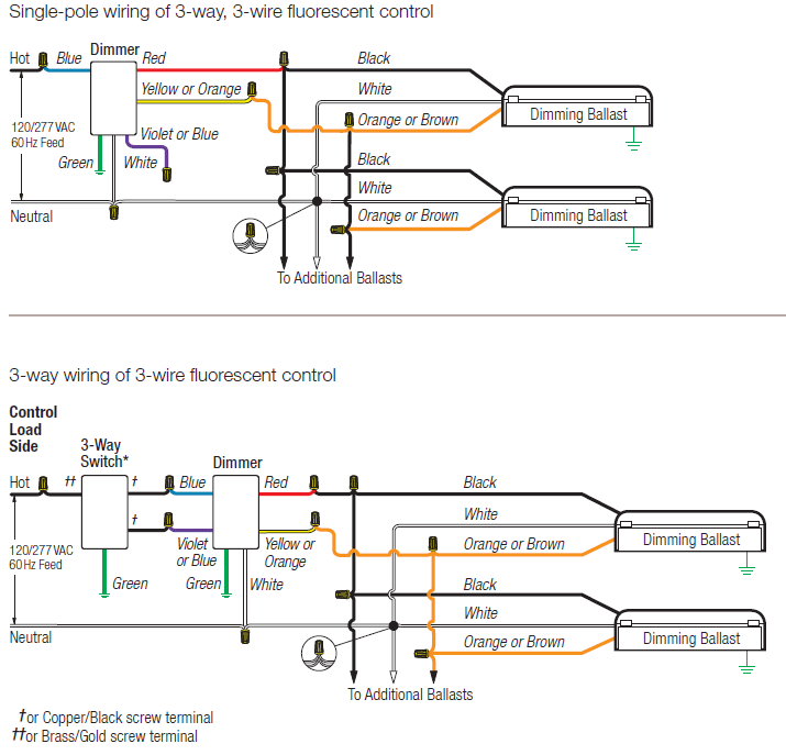
WIRING DIAGRAM.
WARNING, CAUTIONS AND OPERATING INSTRUCTIONS. • To reduce the risk of death, personal injury or property damage from fire.
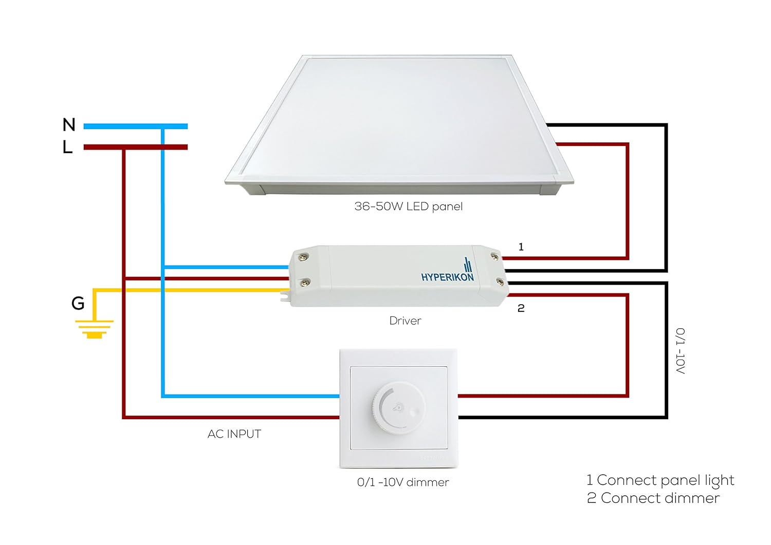
Spec Sheet Lookup. Flat Panel must be connected to a wiring system with an equipment – grounding lines to corresponding wire leads with wire nuts, per wiring diagram. Parts list, installation instructions, & wiring diagrams for all troffer sizes — converting your fluorescent lighting to LED lighting.
Unpack the CR troffer from its shipping container. STEP 2: Including CR14, CR24, CR22 Architectural Troffers.
isuzu 2.3 fuse relay box
1×4, 2×4 wiring diagram (below). Push all.Dec 26, · Metalux 4 ft.
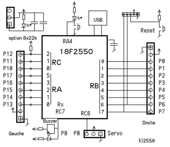
High Output LED Striplight 4SLSTPDDV Review. 2.
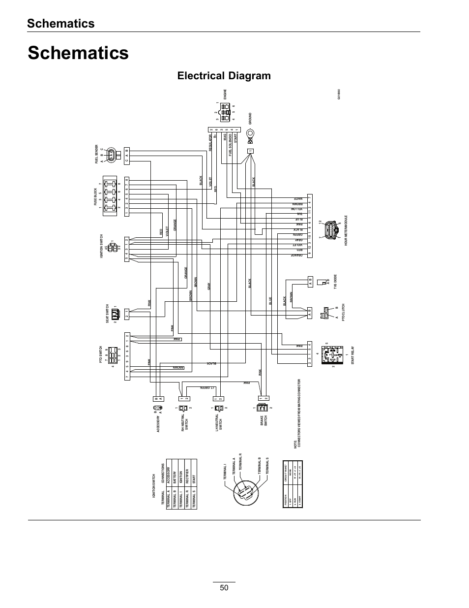
Select the appropriate wiring diagram to connect the emergency ballast to the AC ballast and lamp. Make sure all connections are in accordance with the National Electrical Code and any local regulations.
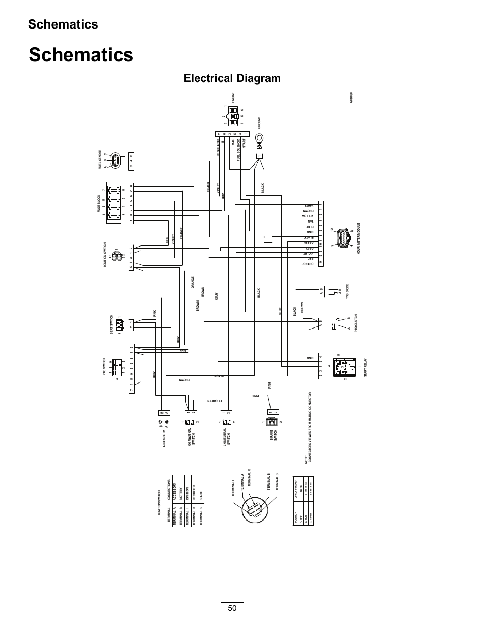
manufacturer. 3. Install the test switch through the ballast channel cover of a troffer or through the side of a strip fixture.
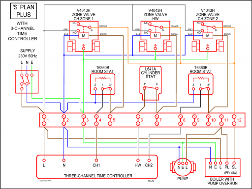
Drill a. The 4 ft. long LED Troffer from Lithonia Lighting delivers general ambient lighting in applications such as schools, offices and hospitals.
Long-life LEDs, coupled with energy efficient drivers, provide extended service life. Low maintenance and easy to install, this troffer works well in applications where LED is desired and budget /5().
LED Troffer Retrofit Kit. Wiring Diagram.
Connecting Driver to AC source supply: Operating temp: 30 F to F. 1.

All units must be individually connected to the AC supply ( VAC): Black = Line. White = Neutral.
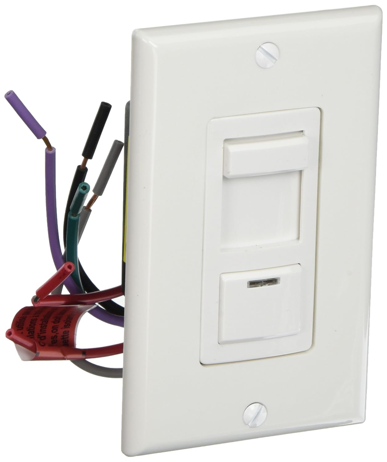
Green = Ground. 2. Line connection to be made to switch lead from source.
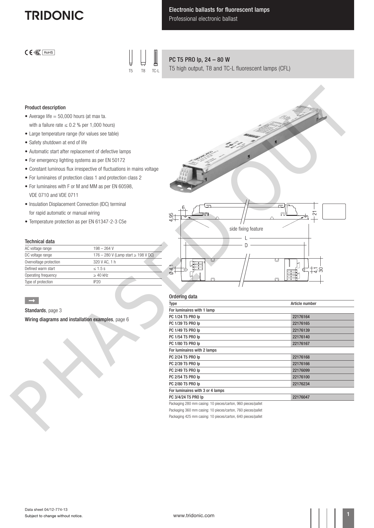
2. WIRING Refer to the wiring diagrams on the back page for the appropriate wiring of lamp(s) and ballast.
Install in accordance with the National Electrical Code and local regulations. For additional wiring diagrams consult Customer Service. Strip Fixture – Select a convenient locatio n on the fixture so the LCTS can be seen afte r installatio.2 x 4 LED Troffer & Fixtures | Cree LightingPhilips DayBrite/Philips CFI FluxGrid LED Luminaire
