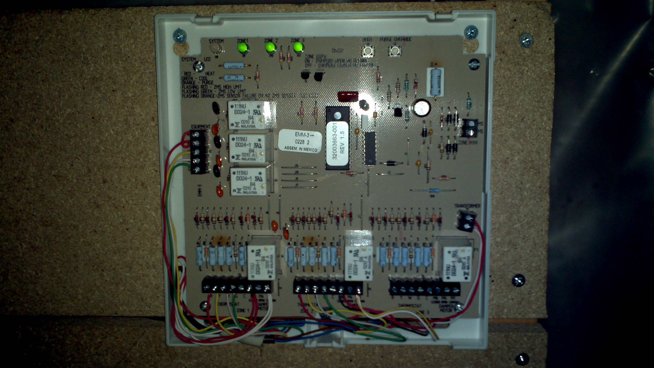
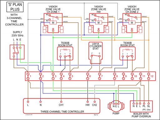
that all zone dampers, zone thermostats, HVAC Controls, power transformer, Outdoor Air (OAS) and Leaving Air Sensor (ZPS) are wired. When installing the MDP3 panel it is important to pick a central location .
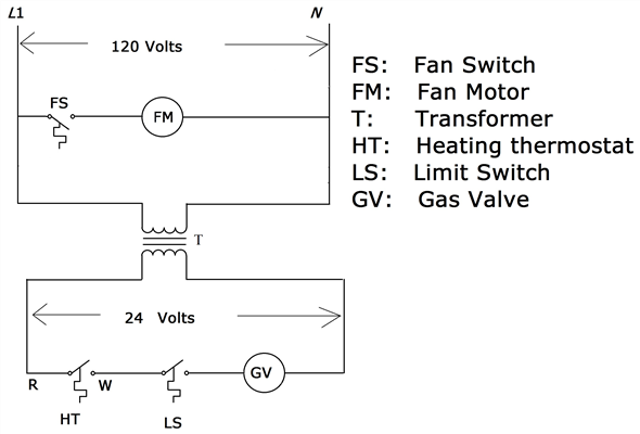
outdoor air temperature and switches the heating control .. WIRING DIAGRAM 2 – Heat Pump Thermostat.
Y. G.
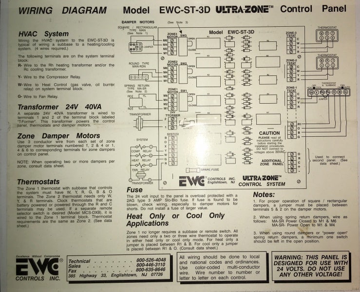
damper in the it’s zone duct to control the flow of conditioned air to the heating or cooling will shut off and all zone dampers will return to DAMPER MOTOR WIRING – This diagram shows. Trol-A-Temp’s typical power open-power closed op-.
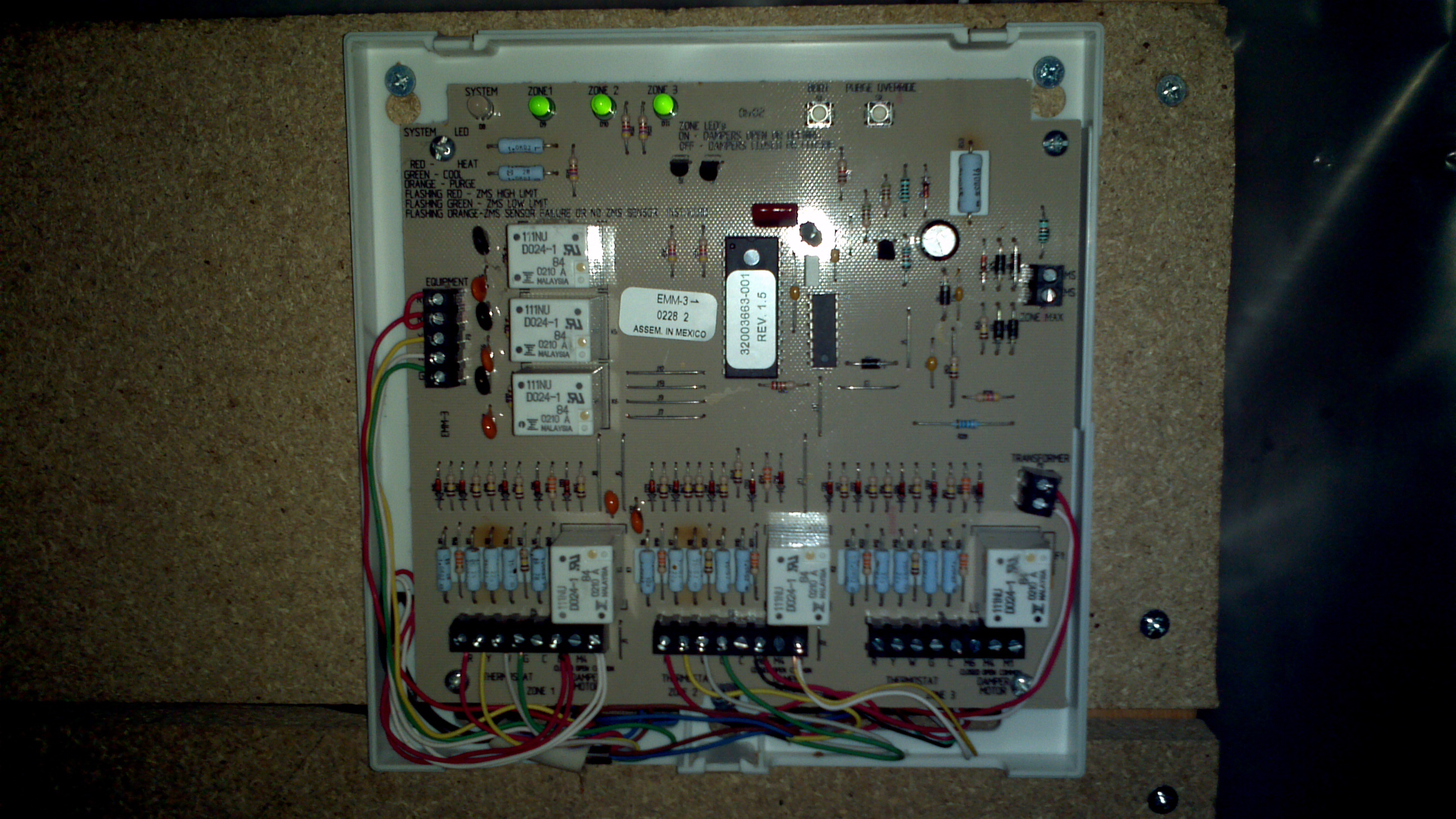
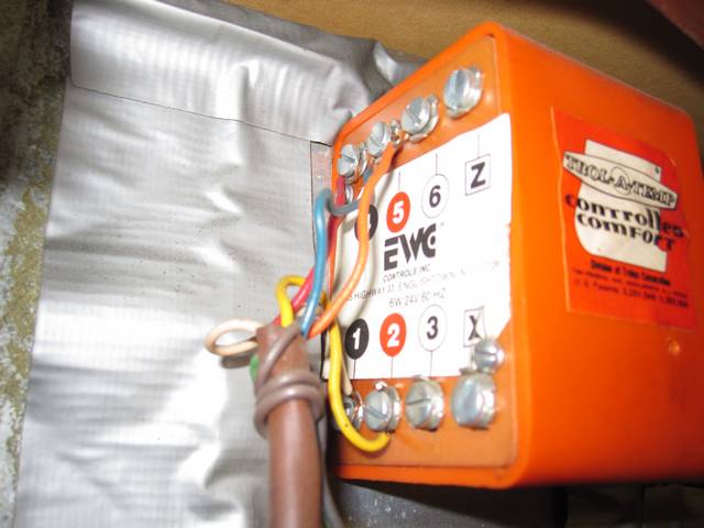
I am in the process of transferring wiring from an old Trol-A-Temp controller to a new I’ve got 3 zones but only got as far as the first damper. The Mastertrol® Mini-Zone™ -2 Zone Control Panel,. Model MM-2 ing) will shut off and all zone dampers will return to their normal DAMPER MOTOR WIRING – This diagram shows.
Trol-A-Temp’s typical power open-power closed op-. panel is the central control panel that all zone dampers, zone thermostats, HVAC location where it is most convenient to bring all the wires.
Most often . Leaving Air Temperature Sensor .
WIRING DIAGRAM 1 – Single Stage Thermostat.Fig. 7. ML Damper Motor Actuator wiring diagram. NOTE: The R relay is not required for operation, but if it is not used, the zone damper LED will be constantly green. Fig.
8. Transformer wiring diagram.
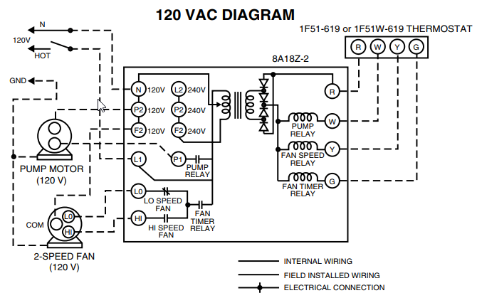
NOTE: A dedicated 40 VA, 24 Vac transformer must be used. Fig.
9. ZoneMAX or C Sensor wiring diagram.
Fig. I am replacing Trol-a-Temp T87F thermostats with Honeywell RTH thermostats.
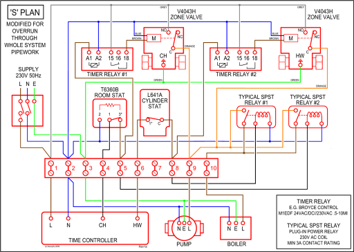
It’s a 3 zone system, with 3 thermostats and 3 control dampers. The current thermostats are wired to a Trol-a-Temp Mastertrol Mini-Zone 3 (MM-3) controller for single stage heating and cooling. DAMPER MOTOR WIRING – This diagram shows Trol-A-Temp’s typical power open-power closed op-posed blade damper motors.
Note the jumper wire required on the motor terminals 2 and 5. Round Spring Return Dampers can also be wired to the MM When using the ARD-PC, wire to the M1 and M6 terminals.
When using the ARD-PO, wire to the M1 and M4 terminals. trol a temp wiring diagram.
Zone Thermostat Heating/Cooling Thermostat and Subbase or Wallplate Model TT OWNER’S MANUAL Page 2. Welcome to the world of energy savings with your new Honeywell Trol-A-Temp Zone Thermostat.Ritetemp and Trol a- Temp wiring Question – schematron.org Community ForumsBy Honeywell Trol A Temp Wiring Diagram | Wiring Library
