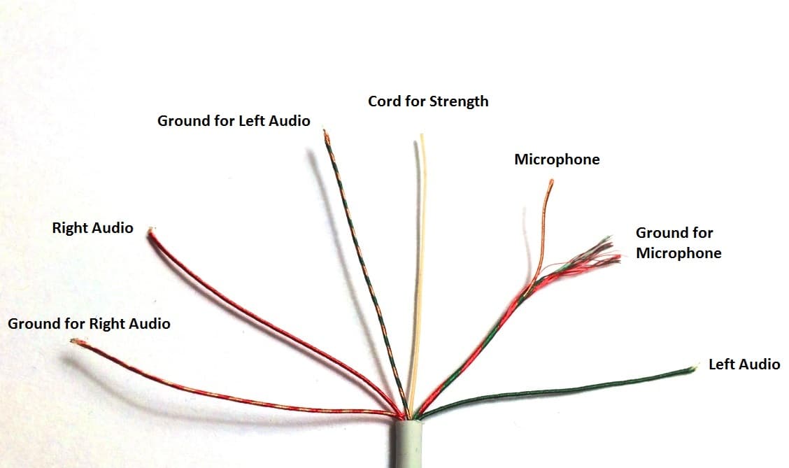
Previously, I wasn’t aware of any commercially available cables to let you connect a line level audio source to the microphone jack of an iPhone/iPad/iPod Touch, so I came up with one of my own.
While it is possible to set your iPhone or iPad next to the radio’s speaker or. Hi, Does anyone have an actual display of the wiring for the stock S4 Headset?
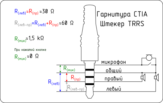
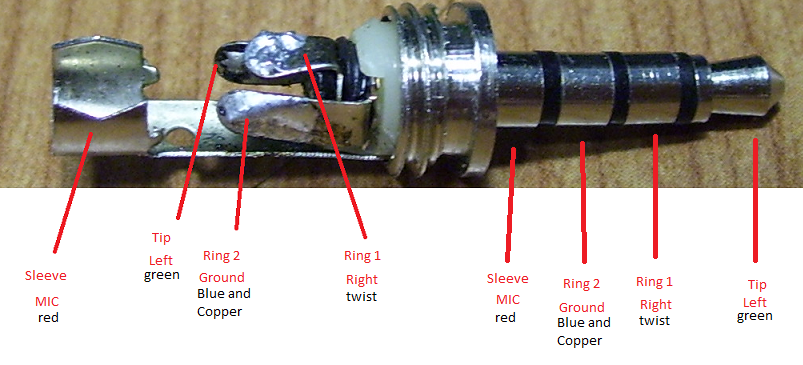
I do know that the TRRS pinout is Left, Right, Ground, Mic. Hi, Does anyone have an actual display of the wiring for the stock S4 Headset? I do know that the TRRS pinout is Left, Right, Ground, Mic.
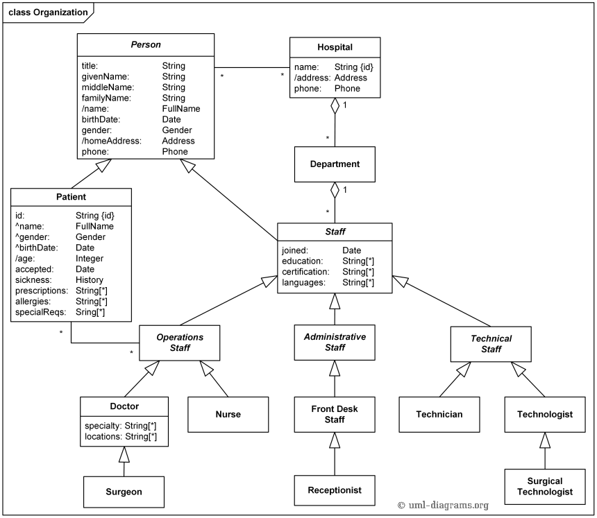
The four wires indicate that it corresponds to right schematic. mm TRRS ( stereo-plus-mic) sockets became particularly common on.
Understanding TRRS and Audio Jacks As you can see from the above diagram , there was a benefit to keeping the TRRS Pinout Examples.Parts Express mm Plug (4 Pole) To 3 RCA A V Cable 6 feet Fulfillment by (FBA) is a service we offer sellers that lets them store their products in ‘s fulfillment centers, and we directly pack, ship, and provide customer service for these products. A TRS connector (tip, ring, sleeve) also called an audio jack, phone jack, phone plug, jack plug, stereo plug, mini-jack, mini-stereo, or headphone jack, is a common analog audio schematron.org is cylindrical in shape, typically with three contacts, although sometimes with two (a 69%(74).
Trrs Connector Wiring Diagram ~ you are welcome to our site, this is images about trrs connector wiring diagram posted by Benson Fannie in Trrs category on Nov 13, You can also find other images like wiring diagram, parts diagram, replacement parts, electrical diagram, repair manuals, engine diagram, engine scheme, wiring harness, fuse box, vacuum diagram, timing belt, timing chain. 3 5mm Trrs Wiring Diagram Free Picture – A PCB Layout is the resulting design from taking a schematic behind specific components and determining how they will physically be laid out on a printed circuit board.

To develop a PCB Layout, you must know the friends of components, component sizes (footprints), and a myriad of further properties (such. jonathangavin, the common assignment for the TRRS connector are Tip – left audio Ring 1 (closest to tip) – right audio Ring 2 – ground Sleeve – microphone Now there are two standards that are being used for the TRRS connector CTIA and OMTB, the only difference is the that ground and mic are reversed – Xbox One Stereo Headset.Fixing the Xbox One Stereo Headset | Pineapple FreefallPhone connector (audio) – Wikipedia
