2-Door Add-on Modules expand the door capacity of a.
TruPortal System either upon initial installation, or as more doors need to be SYSTEM DIAGRAM. The basic control unit possesses IP connectivity and other extension A diagram of a TruPortal solution with a connection to TruVision video recorders.
TruPortal is an IP appliance-based access control system that is integrated with Simple system installation requires no special training. • User-friendly Input/ Output Expansion Module.
Power Supply & System diagram. Note: Use of PoE .
TruPortal offers an IP Appliance-Based Access Control System integrated with the TruVision® line of Simple system installation requires no special training Expanded video: including IP video through the TruVision line System Diagram . Extending the options for TruPortal Access Control System, the Installation of base unit required.
SYSTEM DIAGRAM Expansion Module (board only).The I/O board, the larger of the two, contains the power supply and all field wiring connections. The SOM, the smaller mounted board, contains the main CPU and memory.
TP-SYS-2D: TruPortal 2-Door base kit. Consists of a TruPortal System Controller, installed in UL .
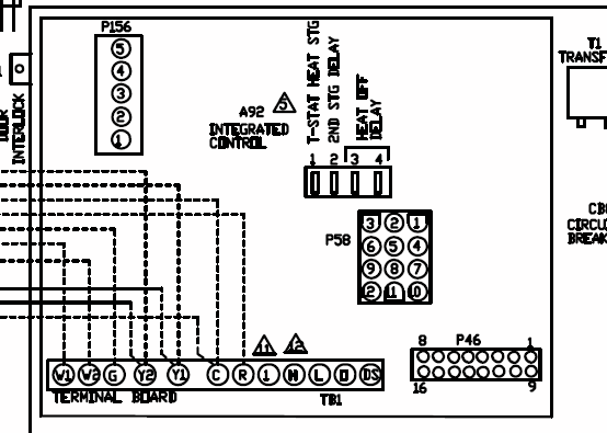
NX-8E Control Panel Installation Manual 5 Terminal descriptions Table 2 below describes the terminals shown in the wiring diagram. Table 2: NX-8E terminals Terminal Description R1 House telephone ring (gray).
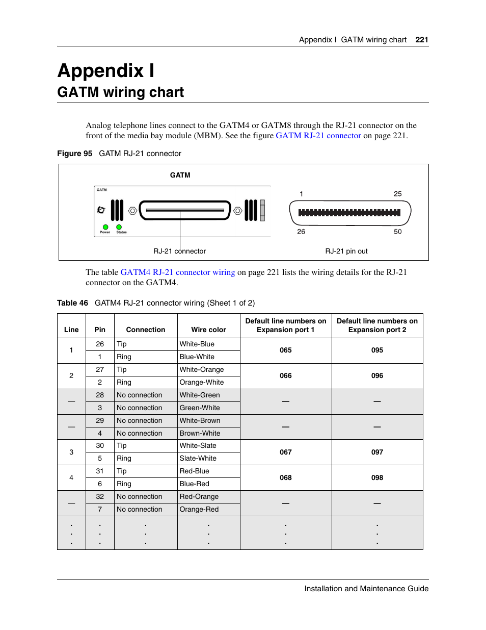
R Telephone ring (red) T Telephone tip (green) T1 House telephone tip . TruPortal System Controller Quick Reference 4 P/N B 26JAN12 en-US should not be connected to the TP-SYS.
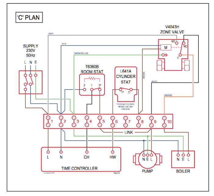
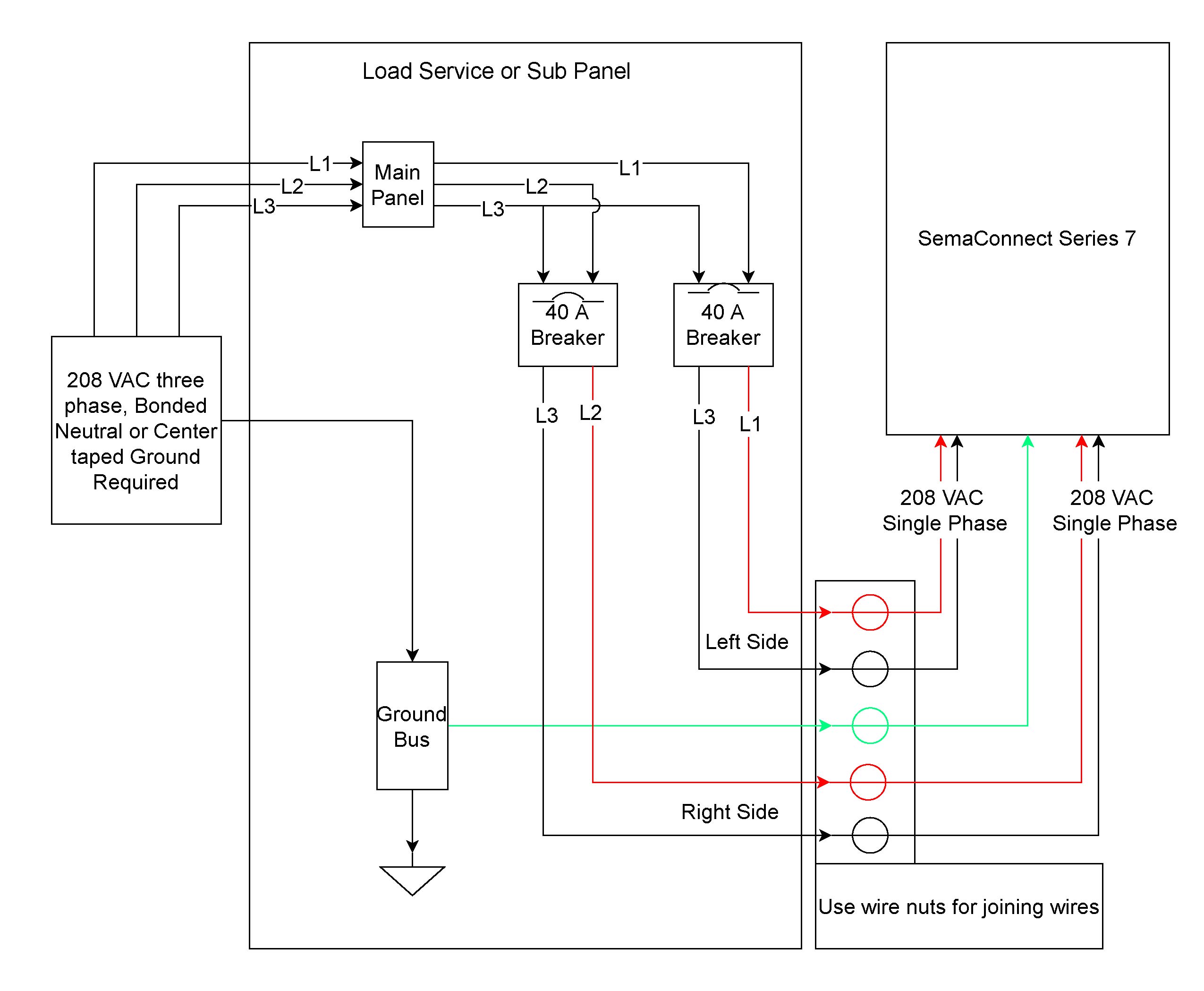
The power supply providing the 12 VDC must have its own backup source. TP-SYS / VAC Power wiring diagram Power connectors The maximum input current is A.
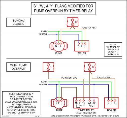
The gauge is dependent on the length of the wire. TruPortal System Controller Quick Reference 3 Communication Wiring To access the network, connect the Ethernet cable to the System Controller using Ethernet Port 1 or Ethernet Port 2.
(Ethernet Port 2 is a backup port with a fixed IP address: ) To connect additional I/O panels via the SNAPP bus, use the two-. DMP LTE-V5 Cellular Module Now Supports the XR and XR Panels November 30, — LTE-V5 Cellular Module Now Supports the XR and XR Panels For customers wanting to upgrade legacy XR and XR panels, there.TruPortal 2-Door Add-on Module | Access Solutions | Interlogix Global Security ProductsUser Manual APAX PC-based Controller with Atom Dual Core CPU
