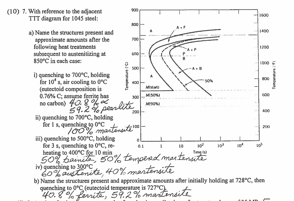
Download scientific diagram | Time Temperature Transformation (TTT) diagram of AISI steel [9] from publication: The 2D Finite Element Microstructure.
The Physical Metallurgy of Steel by W.C. Leslie (McGraw Hill).
The ASM .. The equilibrium binary Fe-C phase diagram depicts the phase fields that involve graphite and the solid . , and in the A.I.S.I.
system. Heat Treatment of Steels.
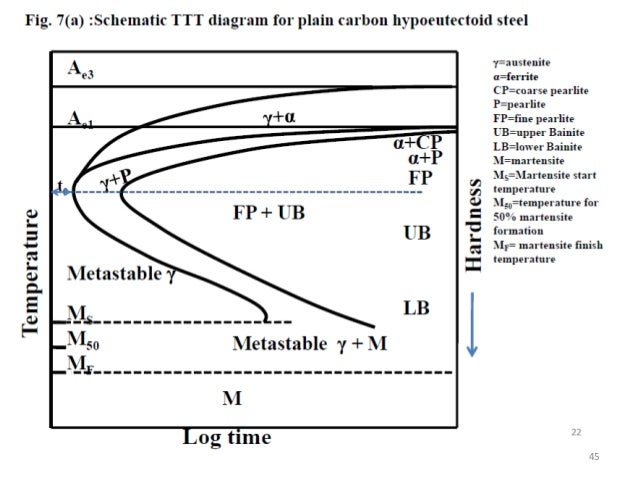
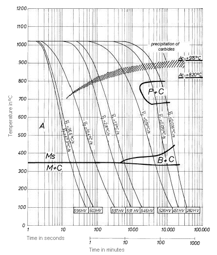
MSE Lab IV AISI-SAE – % C. ▫ AISI- SAE Therefore, a CCT diagram’s transition lines will be different than a.
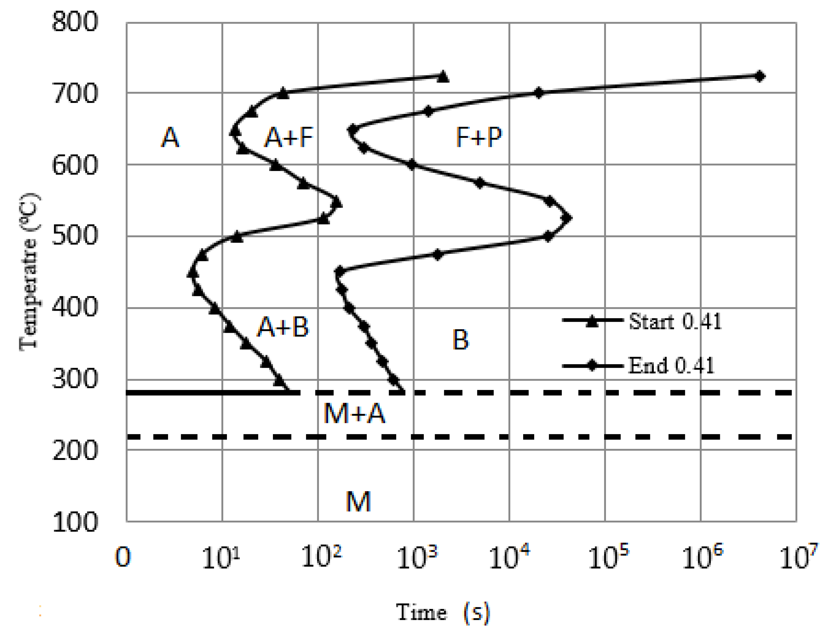
Answer to A TTT diagram for steel is given. Assume specimens are small samples of normalized steel.
What microstructures. Heat Treatment of schematron.org – Download as PDF File .pdf), Text File .txt) or read online.
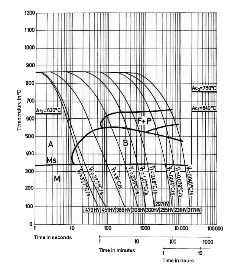
TTT diagram for eutectoid steel shown in relation to the Fe–Fe 3.Dec 13, · RE: Bainitic Steel, AISI metengr (Materials) 21 Sep 04 As a follow-up, I reviewed the CCT/TTT diagram for an AISI Type carbon steel and it would appear that the ferrite/austenite upper nose protrudes before the bainite nose, meaning you would form ferrite before the bainite transformation is completed.
In Fig. 1 is a TTT Diagram for Carbon Steel.
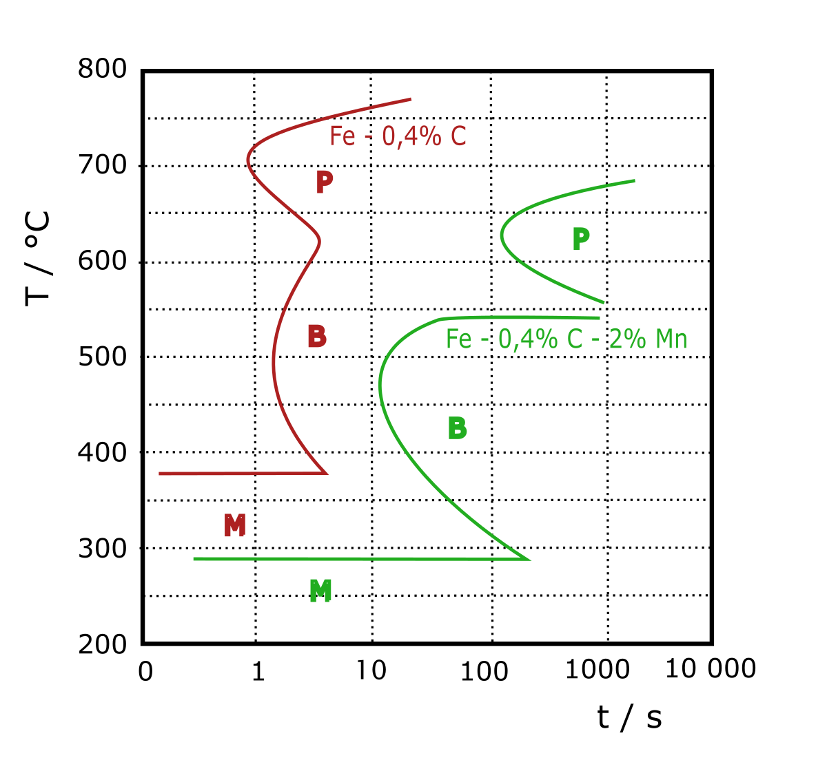
As mentioned earlier in this document (Chapter 1), basically heat treatment of steels should be regarded as the accurate technique to change the „Structure“ of the steel 5/5(1). CCT diagram can be converted to TTT diagram.
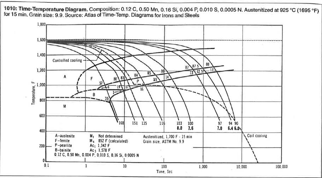
cross multiplying and differentiating We get τTTT (TCCT)=1/(f2(TCCT) df1/dTCCT) Equation 5 or 7 can be used for the conversion of CCT diagram to TTT diagram depending on constant cooling rate or case of cooling rate that can be expressed in analytical or empirical form. transformations in steel. It illustrates how to use an equilibrium phase diagram, TTT curves, ITT curves and CCT curves to specify a heat treatme nt, understand the development of a microstructure and, to a lesser extent, the relationship between microstructure and .
4 Introduction to Heat Treatment of Plain Carbon and LowAlloy Steels Additional reference material: Dowling, Section A map of the relevant portion of the equilibrium phase diagram for the FeC system is shown in Figure 1, showing the combinations of temperature (vertical For steel, the quenching medium is water at ambient.Heat Treatment of Steels – ppt video online downloadBainitic Steel, AISI – Metal and Metallurgy engineering – Eng-Tips