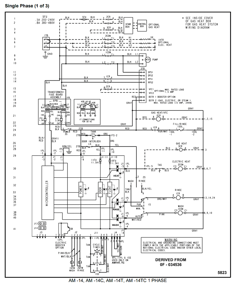
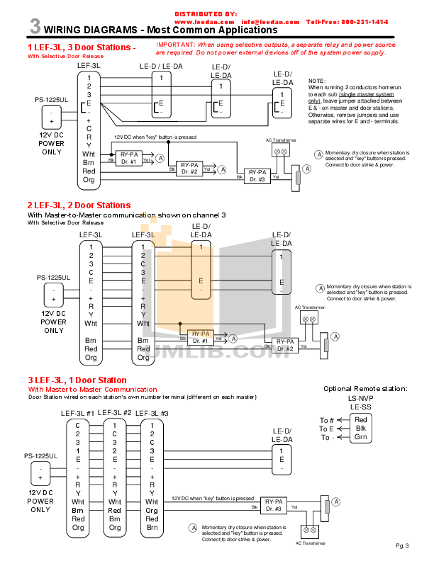
Max current: mA. DC Sink Inputs Wiring Diagrams.

External Power. Internal Power.
Max current: mA. Relay and Transistor Outputs Wiring Diagram.

TWDLCAE40DRF compact PLC base . DC Source Inputs Wiring Diagrams.
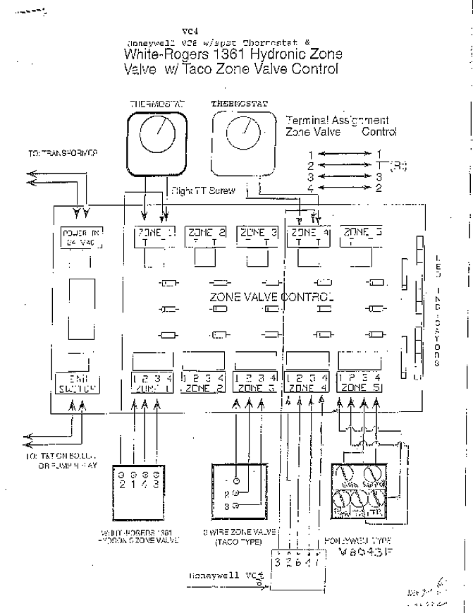
External Power Relay and Transistor Outputs Wiring Diagram. Results 1 – 48 of TWDLCAE40DRF.
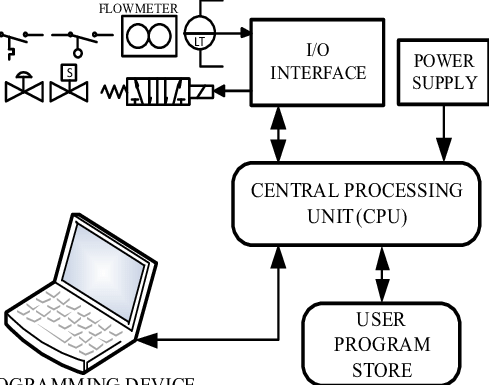
CPU compacta Twido – alimentacion V. Relay and Transistor Outputs Wiring Diagram.
Performance Curves. TWDLCAE40DRF compact PLC base Twido TWDLCAE40DRF has not been replaced.
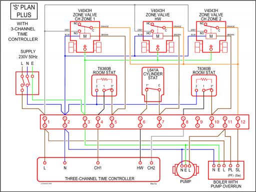
Please contact your . Relay and Transistor Outputs Wiring Diagram. TWDLCAE40DRF (45 70).

Twido V 24inn/16ut relé/tr,skru, Eth . Relay and Transistor Outputs Wiring Diagram.
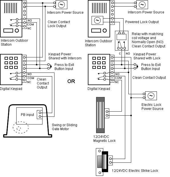
Performance Curves. I/O Usage Limits.Analog I/O Modules Hardware Guide 05/ 2 05/ Schneider Electric assumes no responsibility for any errors that may appear in this document.
If you have any suggestions for improvements or amendments or have Specifications and Wiring Diagrams for Analog Input Modules TMCE40R – controller M 40 IO relay Ethernet. Products.
View the new All Products menu. View the new All Products menu.
Looking for product documents or software? Go to our Download Center.
Wiring Diagram (Negative Logic) (*) Type T fuse. Connection of the Fast Inputs. I0, I1, I6, I7.
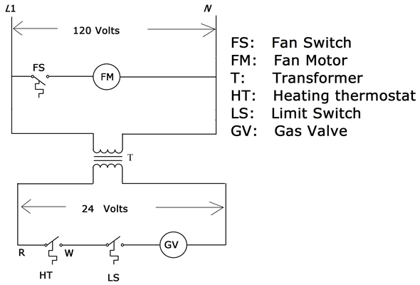
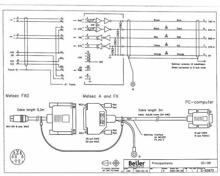
Relay Outputs. – PLC Communication cables pin diagram twido.
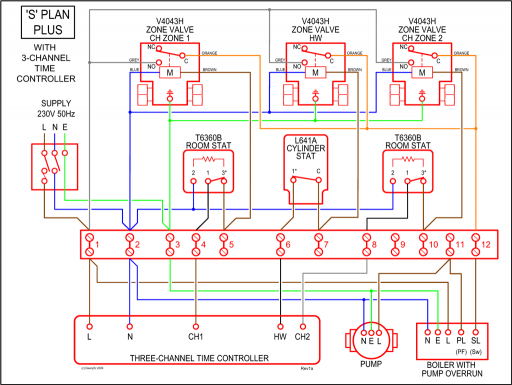
Abstract: TWDLCAE40DRF manual twido TWDLCAE40DRF twido TWDLCdE40DRF TWDLCDE40DRF twido plc cable pin diagram RS TWDLCAE40DRF TWDLCAE40DRF COMMUNICATION CABLE PLC programming Canopen of twido TWDNCO1M – zelio plc wiring diagram cable. AC Power Supply Wiring Diagram DC Source Inputs Wiring Diagrams External Power Internal Power Max current: mA.
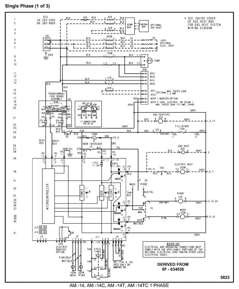
DC Sink Inputs Wiring Diagrams External Power Internal Power Max current: mA. Relay and Transistor Outputs Wiring Diagram.
Twdlcae40drf wiring diagram
7. 8 Product data sheet Performance Curves TWDLCAA24DRF.
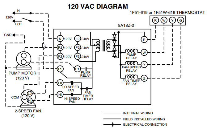
Twido programmable controllers Hardware Reference Guide TWD USE 10AE engVersion me, please Twdlcae40drf wiring diagram thinkTelemecanique LC1 Contactor and LR2 Overload Relay Replacements