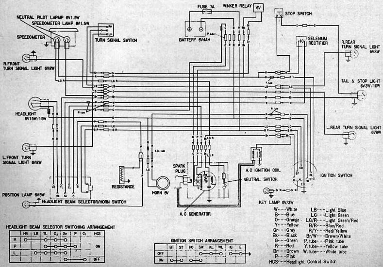
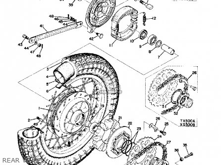
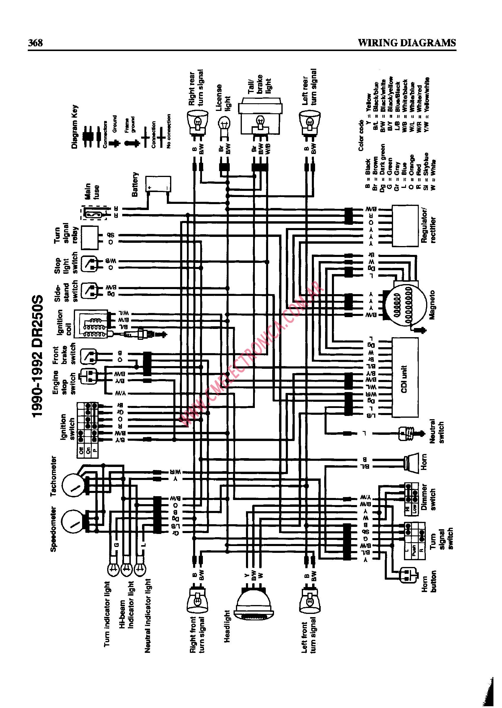
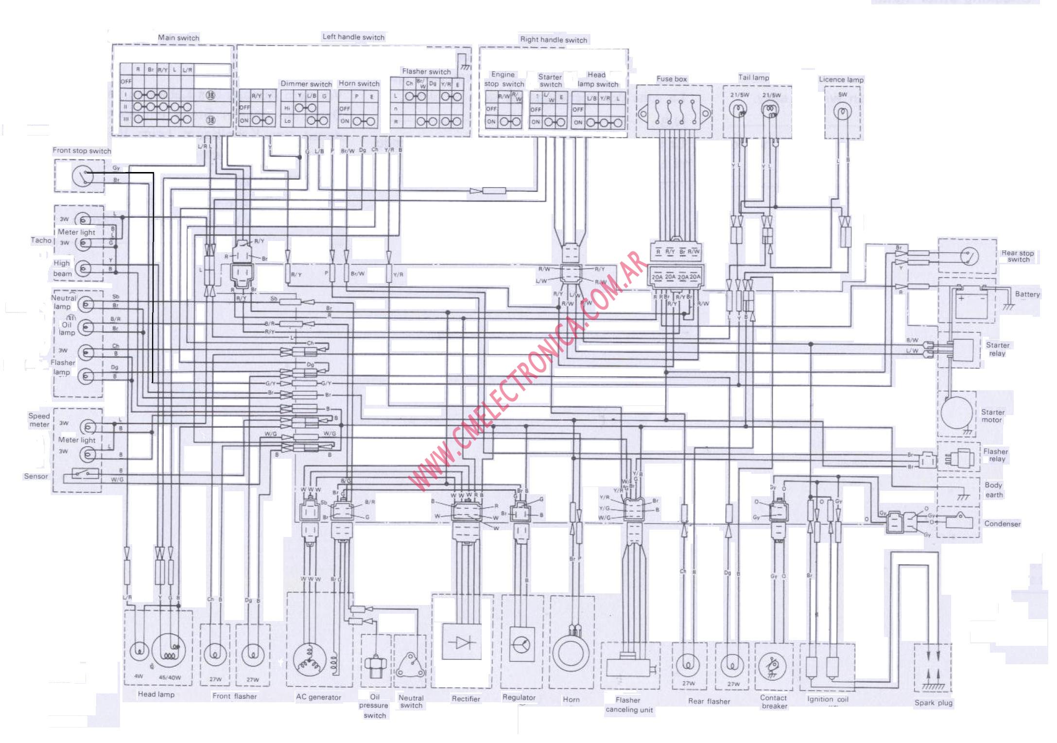
Yamaha AT3 Electrical Wiring Diagram Schematic HERE. Yamaha Yamaha TX TX Electrical Wiring Diagram Schematics HERE.
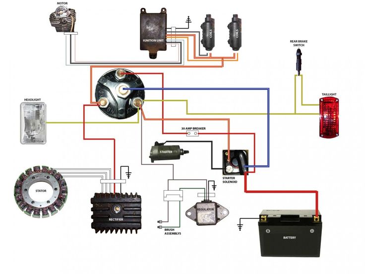
Flight controller wiring (Take UART4 for example). BFOSD 25mW TX Manual.
4R7. 0. Instruction diagram.

Channel. CH1.
CH2. CH3.

CH4. CH5.
Yamaha TX manual. Author Topic: Yamaha TX manual (Read times) Re: NEED A TX manual. «Reply #1 on: Dec TX HMI / PLC Series.
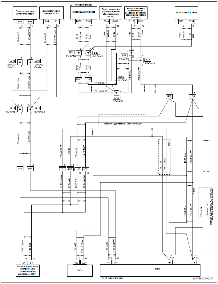
” Display – CODESYS . The adjacent wiring diagrams show the respective pin as- signments.
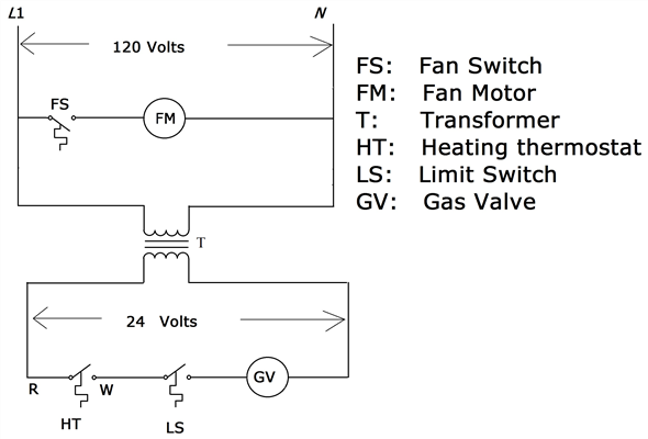
Attention: In the. Yamaha AT3 Electrical Wiring Diagram Schematic HERE.
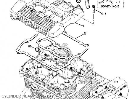
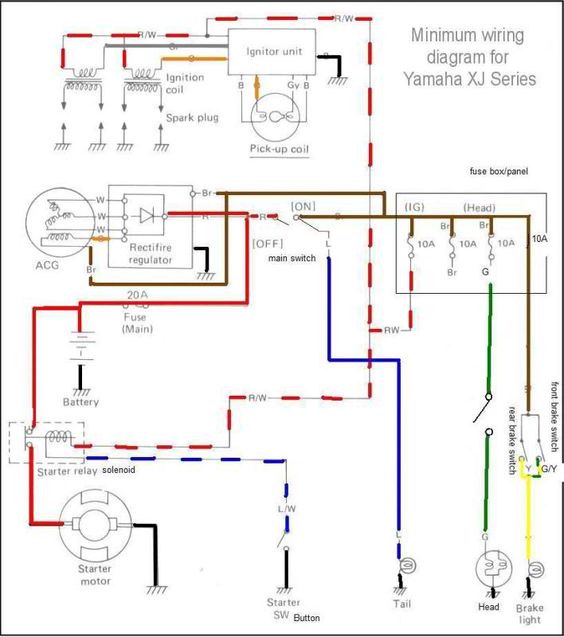
Yamaha Yamaha TX TX Electrical Wiring Diagram Schematics HERE.Feb 10, · Sort of a layman’s approach to making sense of all that mumbo jumbo. A wiring diagram is a simple visual representation of the physical connections and physical layout of an electrical system or circuit. It shows how the electrical wires are interconnected and can also show where fixtures and components may be connected to the system.
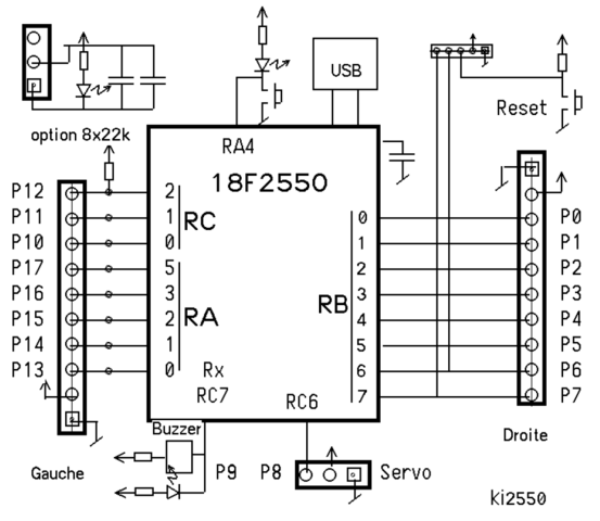
for TX transmitter. If you don’t have any spare magnet wires check Radio Shack.
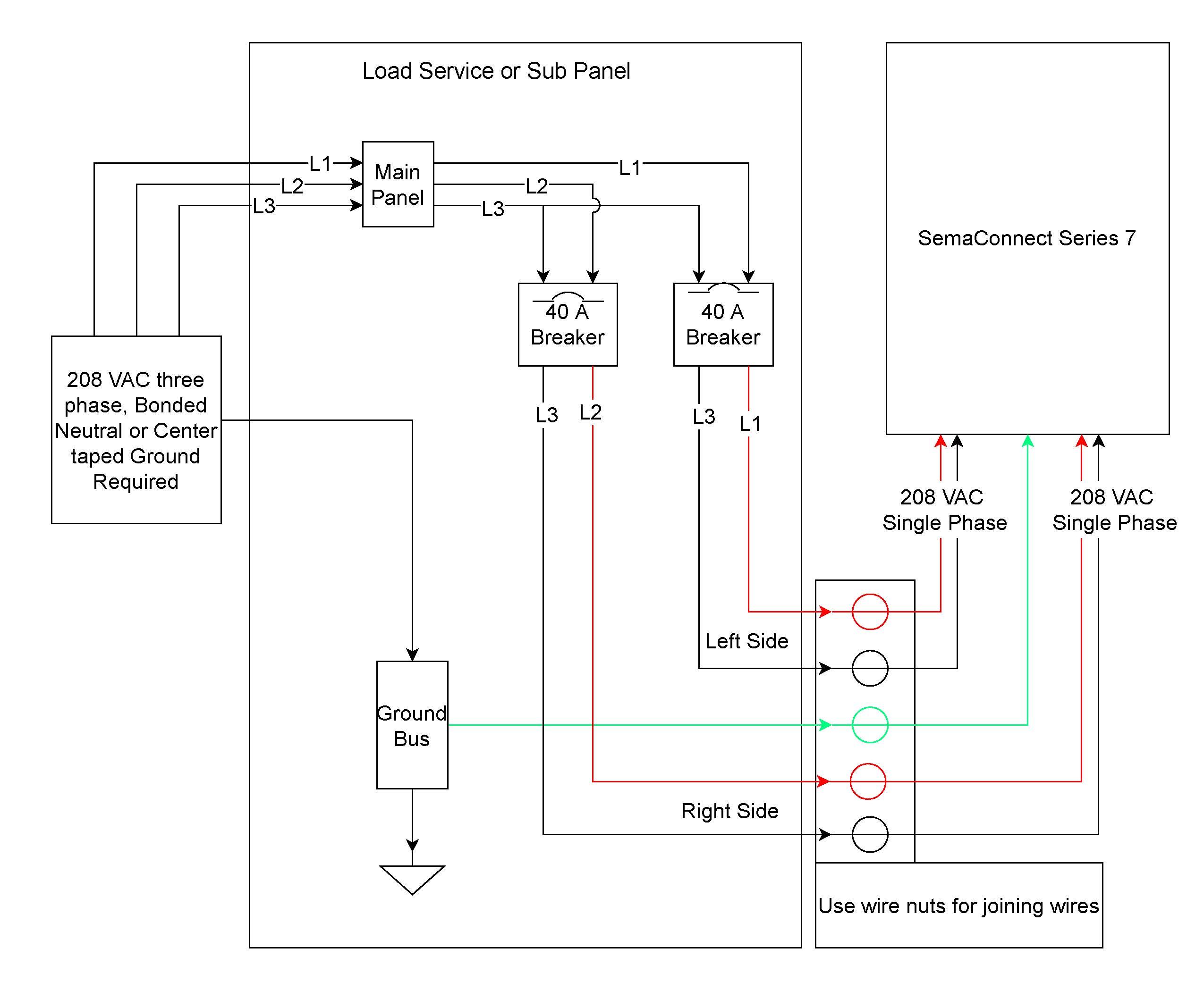
They sell three spools of magnet wire for around $5. The coil pack purchased from Radio Shack includes 14 meters of 22AWG mm) wire, 25 meters of 26AWG (mm) wire and 65 meters of 30AWG (mm) wire.
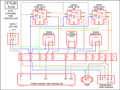
Miniature ferrite beads are used for amplifier schematron.org Navigate your Yamaha TX schematics below to shop OEM parts by detailed schematic diagrams offered for every assembly on your machine. OEM is an acronym for original equipment manufacturer, which means that the Yamaha TX OEM parts offered at schematron.org are genuine Yamaha parts/5(K).
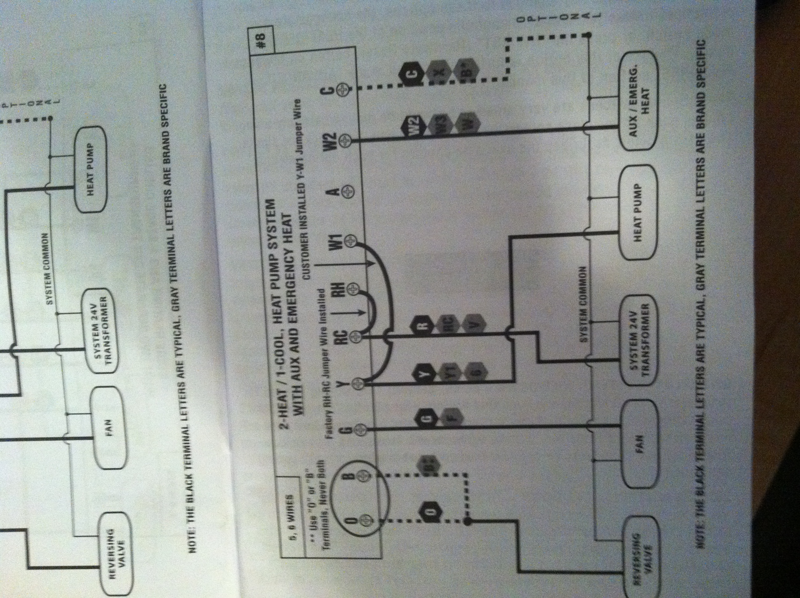
WIRING DIAGRAM NOTES: (Important, please read all notes before connecting wires) • If the information provided in the following wiring diagrams does not clearly represent or match your system, please refer to the “TECHNICAL ASSISTANCE” section of this manual, and contact us before removing any of your existing thermostat wiring.Errors in Yamaha TX wiring diagramTX mW FM Transmitter | Circuit Wiring Diagrams
