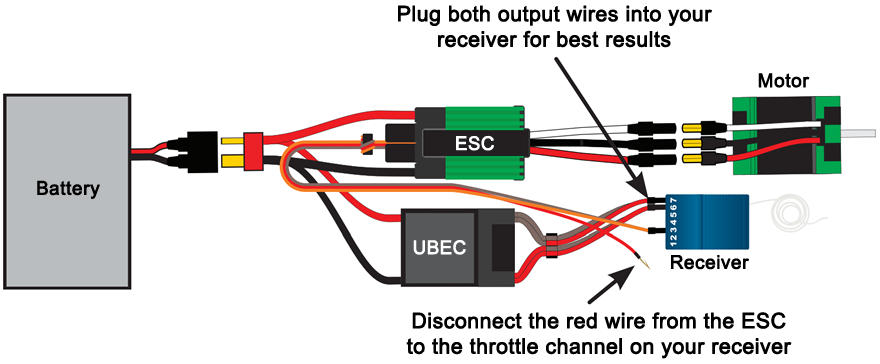
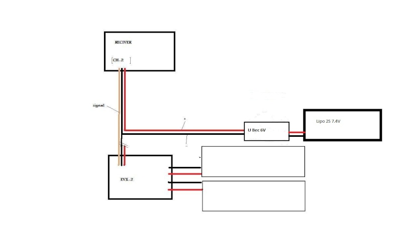
Question Proper wiring for a UBEC Power Systems. OK so i hooked everything up as above diagram and everything works, however but my.
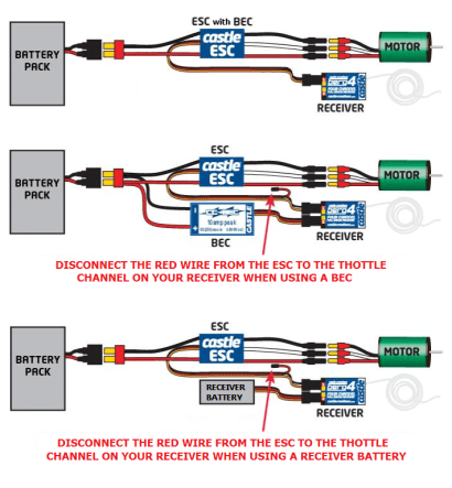
A fellow youtuber asked me to put this vid together This is a quick “how to” on hooking up an external UBEC to your existing ESC, which. I found this wiring diagram showing the wiring of a ubec, spc, and optima.
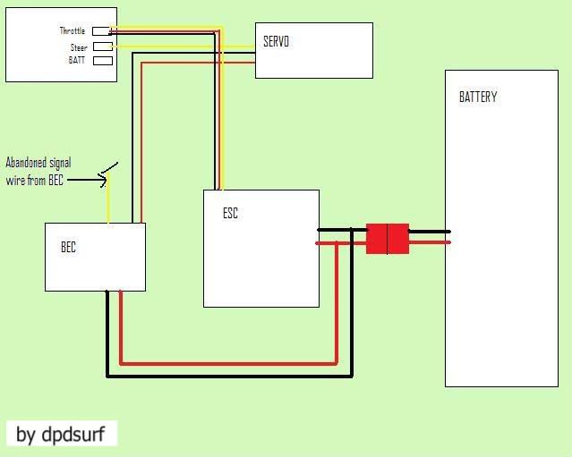
little confused – if you look closly it shows TWO blk and TWOred bullet. I found this wiring diagram showing the wiring of a ubec, spc, and optima.
little confused – if you look closly it shows TWO blk and TWOred bullet. I found this wiring diagram showing the wiring of a ubec, spc, and optima. little confused – if you look closly it shows TWO blk and TWOred bullet.Aug 21, · Using a 3A UBEC is a safer way to go on large models for the following reasons: 1.
Most built-in BEC circuits are 1 to 2 amp ‘linear mode’ circuits which are only useful for 2 or possibly 3 standard size servos when using a 3 cell Lipo battery. Apr 04, · if the BEC of your ESC is to weak to support the servo, you ll need a UBEC schematron.org schematron.org Users need to disconnect the built-in BEC output on the brushless ESC; disconnect the red wire in the ESC control cable (refer to the diagram below), then connect the input end of the UBEC to the battery wires in parallel, and plug the output end (of the UBEC) into any unoccupied channel of the receiver last.
How to wire up a UBEC with an ESC that has a built in BEC Connectors Motor Receiver Please note that the red/orange (+ve) wire from the ESC (Electronic Speed Controller) to the receiver is broken. Rather then cut the wire, carefully remove the wire and pin from the plug and tape it back out of the way so that you can re-insert it at a later day.
female contacts. See Wiring Diagrams on page 8 for contact positions and wire colors for the UBEC 1S. Wiring UBEC 1C Controller(s) For a single UBEC 1C controlling one valve: Connect power and ground to the controller.
Use 1 amp fuse for 12v ( amp for 24v) on positive controller leads.EdgeTriXX Build Log | EdgeTriXXUBEC – Tutorials