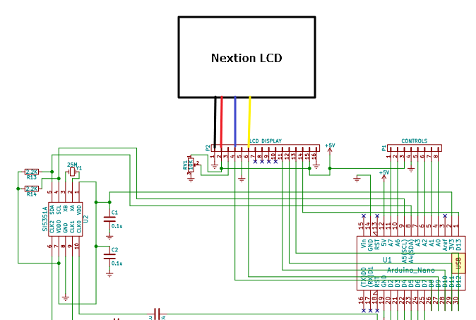
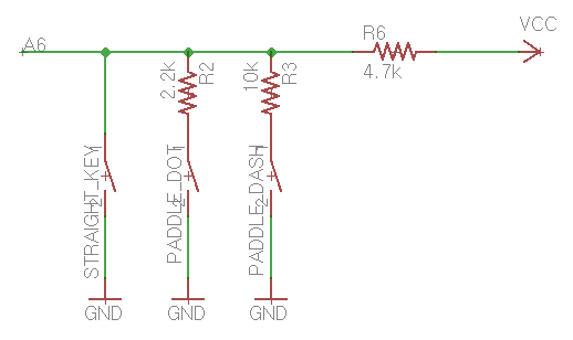
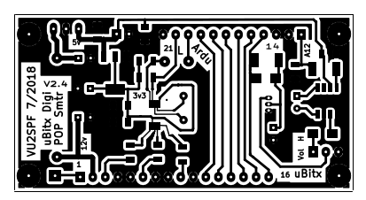
The cause can be found in the schematic below. (ignore red, yellow, green wires, there is for just my work). Connect 5Volt and However, in the case of uBITX, it would be very difficult to operate the reset switch.
I suggest. to wire it up.
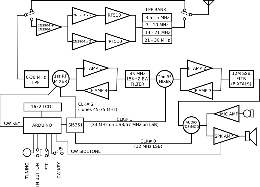
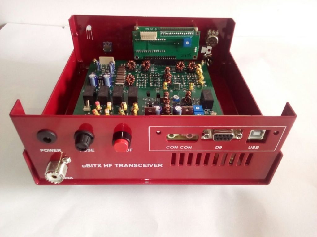
Missing is any kind of case, this being left to the imagination of the user. I discovered an error in their wiring diagram.
They had. Universal Case DA Grey Structure.
Rated out of 5. $; Universal Case Blue & White For uBITX.
Rated out of 5. $; Multiband Band Pass Filter .
The cause can be found in the schematic below. (ignore red, yellow, green wires, there is for just my work).
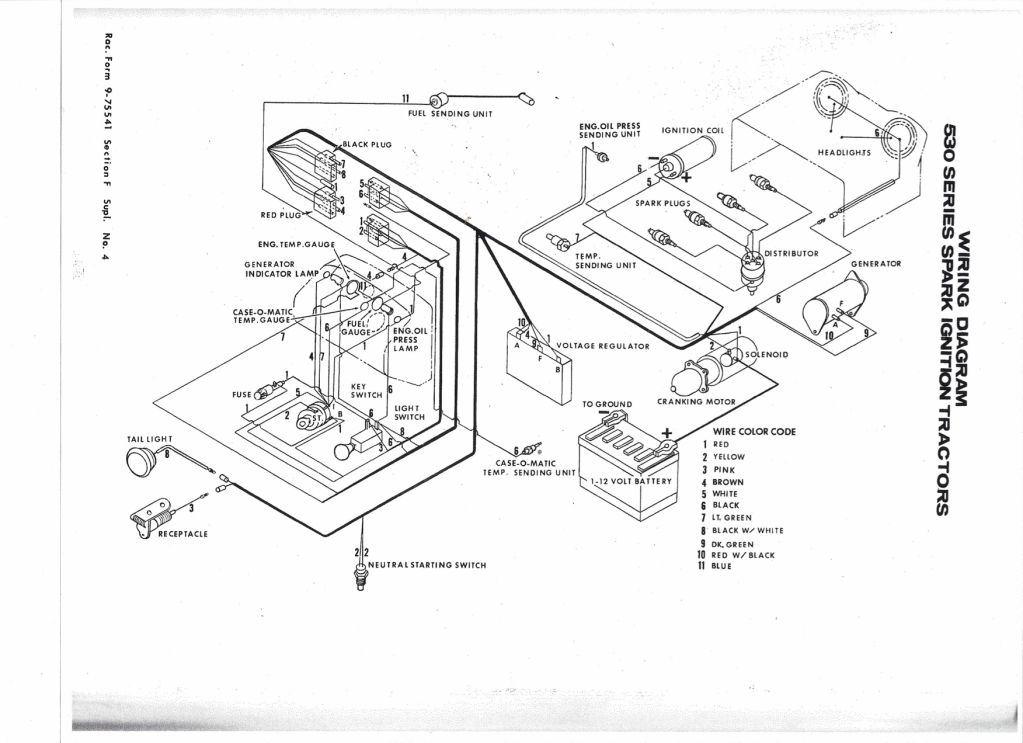
Connect 5Volt and However, in the case of uBITX, it would be very difficult to operate the reset switch. I suggest.
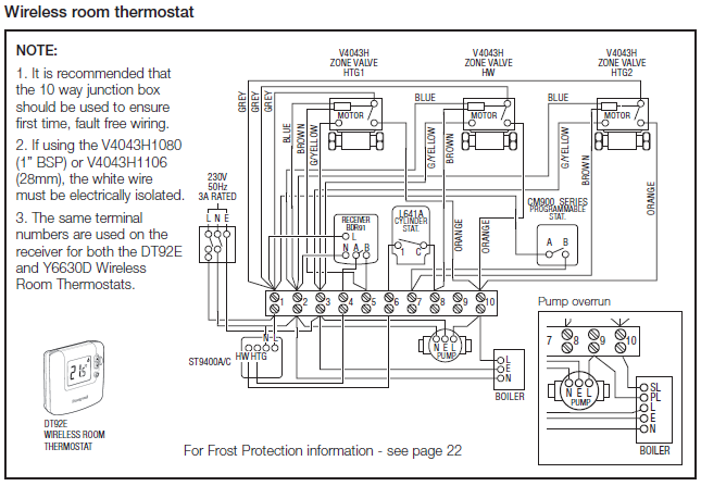
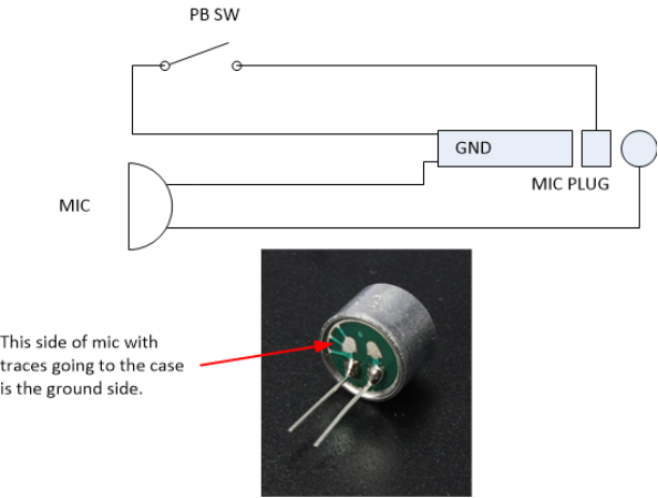
Does anybody have a diagram or description of the mic wire up for the uBITX? Looking at the uBITX schematic and a mic wireup for an older version of BITX .
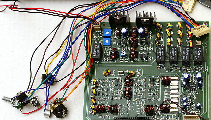
Ideally in such a case the PTT would probably also have two.Step 4: Wiring up the Audio connector. The audio connector is another 8-pin connector. It connects to the main board of the µBITX.
It connects the mic, headphones and the volume control to the board. Write ‘Audio’ on the top of the connector to prevent swapping it with the digital connector.
Step Wiring up the Volume Control. I thought I should try and get it corrected again – at least show a picture of how it needs to be (if they follow the Wiring UP diagram).
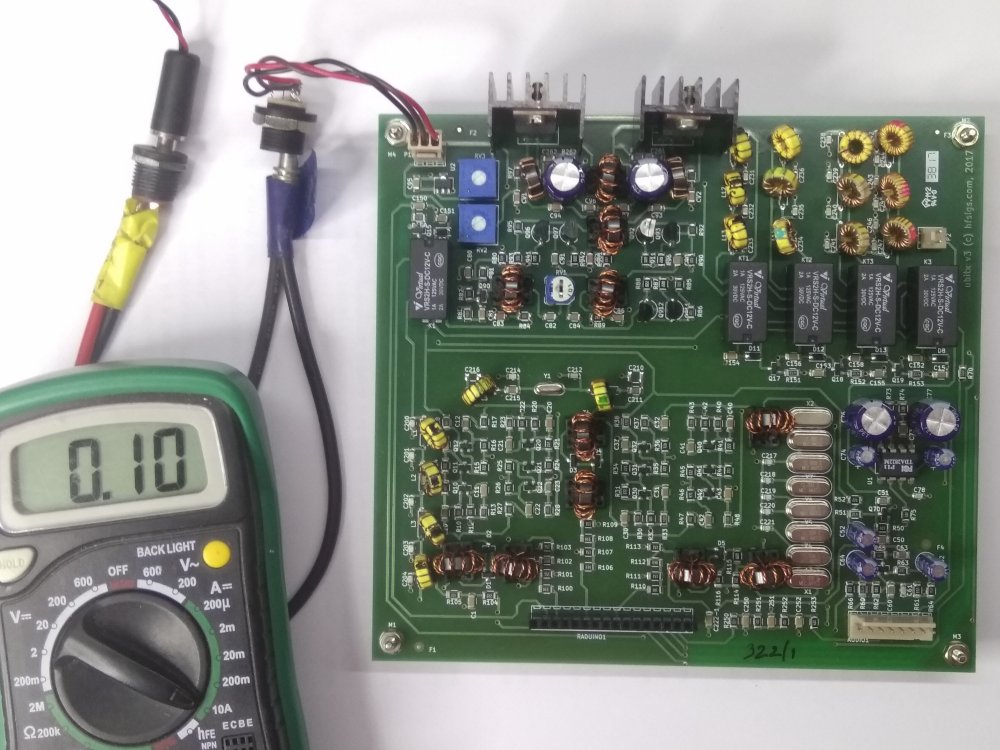
I made up that little example (disregard the color code on the resistor I used (it isn’t a K) for the example. Farhan has just released the Firmware, Schematics, and Wiring Diagram for the production version on GitHub.
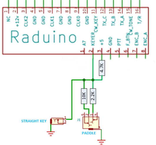
Arduino Sketch: 3 Responses to The uBITX Transceiver: An Update. Good case design of ubitx and also great info.
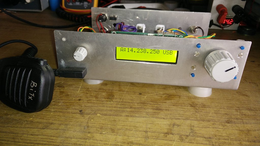
keep it up and good wishes. Norm.
Lee says: January 26, at am Hi, what are the dimentions of the pcb for the. Assembly of the µBitx transceiver typically takes between 8 and 20 hours. The majority of the time is spent on selection of the enclosure, knobs and power supply, and in creating holes for insertion of components on the front and back panels of the enclosure. May 07, · A few months back I order my uBITX QRP radio and finally had the time to build it all.
I had a very hard time as a new amatuer radio operator / new to building radio finding resources to help.µBITX – Wire up – HF SIGNALSµBITX – Wire up – HF SIGNALS