Wiring up the Mic jack.
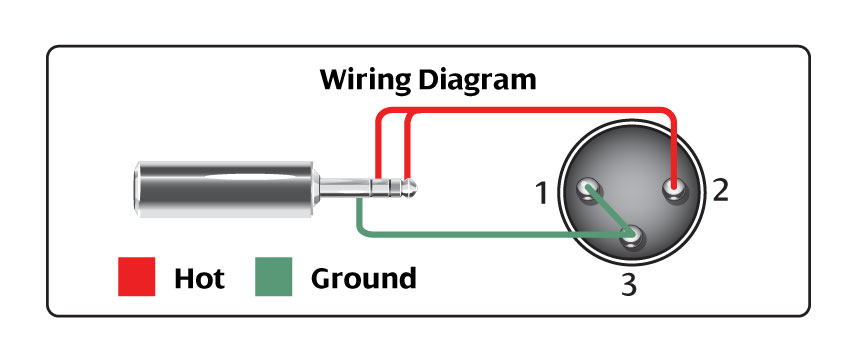
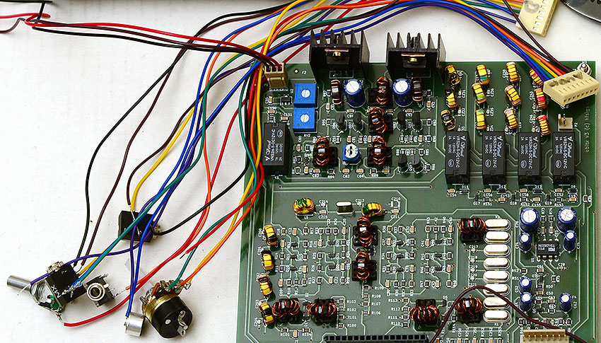
Mic wiring diagram: See the photo below for an example of how to wire up the microphone jack. Photo thanks to Randy KM4PNO.
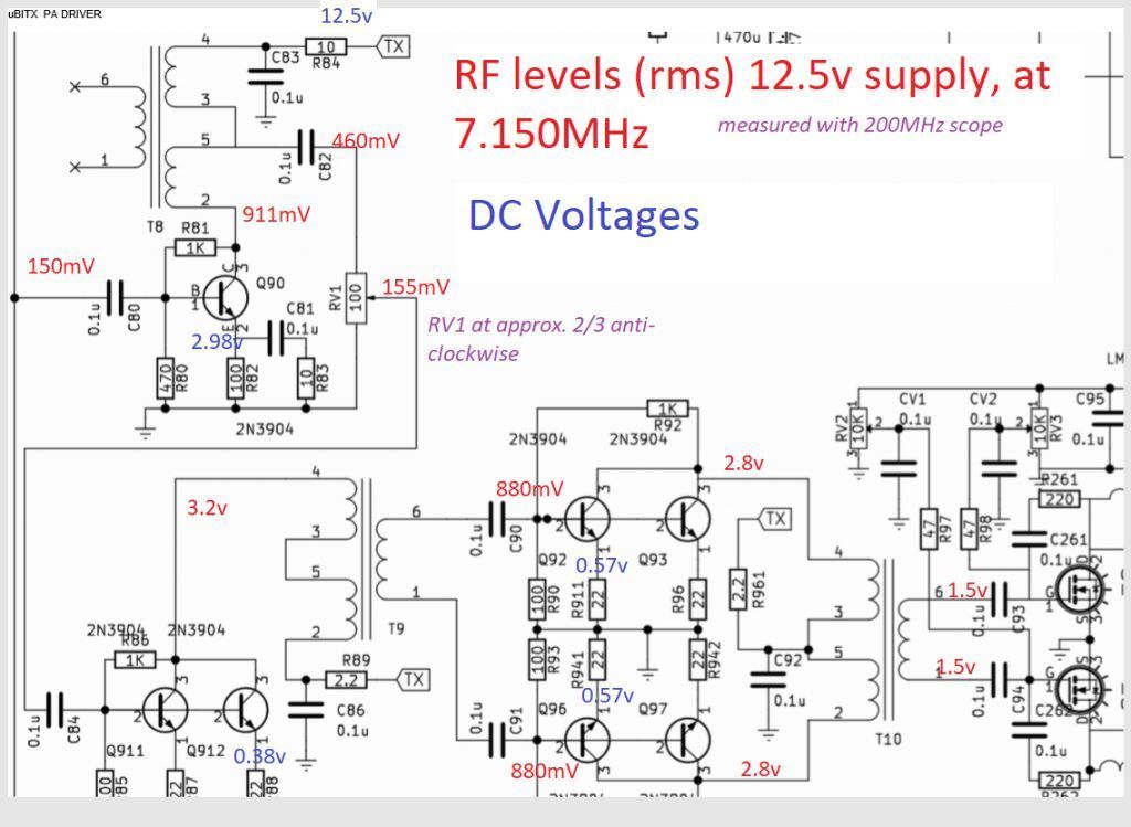
schematron.org Farhan has just released the Firmware, Schematics, and Wiring Diagram for the production. This directory contains modifications that KB1OIQ has done to his // uBITX QRP by Ashhar (VU2ESE) Farhan schematron.org: * Circuit schematic of the uBITX.
Robert’s uBITX QRP transceiver kit with fire red chassis. .
Farhan has just released the Firmware, Schematics, and Wiring Diagram for the production version. uBITX.
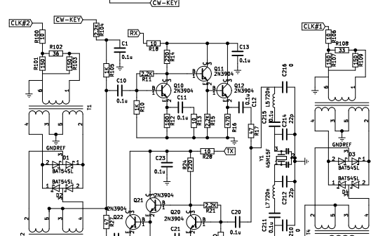
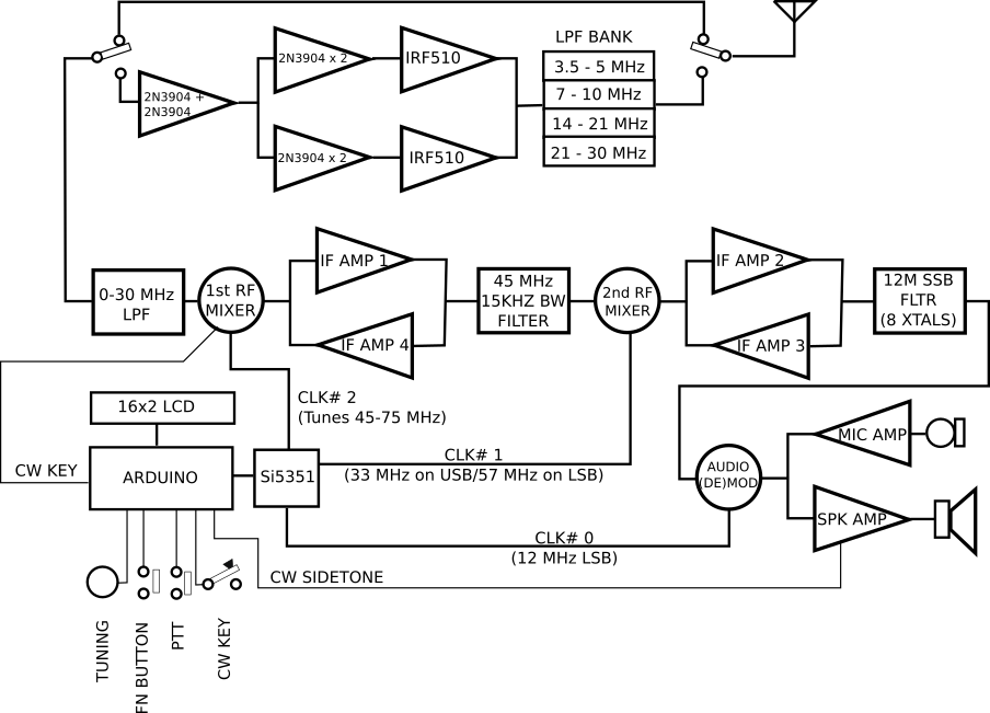
From India, Ashhar Farhan VU2ESE. schematron.org Page 2. uBITX FUNCTIONAL DIAGRAM. Page 3.
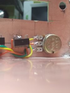
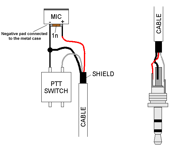
uBITX WIRING TO BE DONE.I am attempting to wire up the provided eletrect mic and ptt on for a ubitx to a mm plug. However, I have no idea what wires to connect where in order to get it working properly.
My attempts to find a guide online have been unsuccessful, people just post pictures of completed mics where I cannot see the wiring. He didn’t connect the USB 5v power into the Raduino).
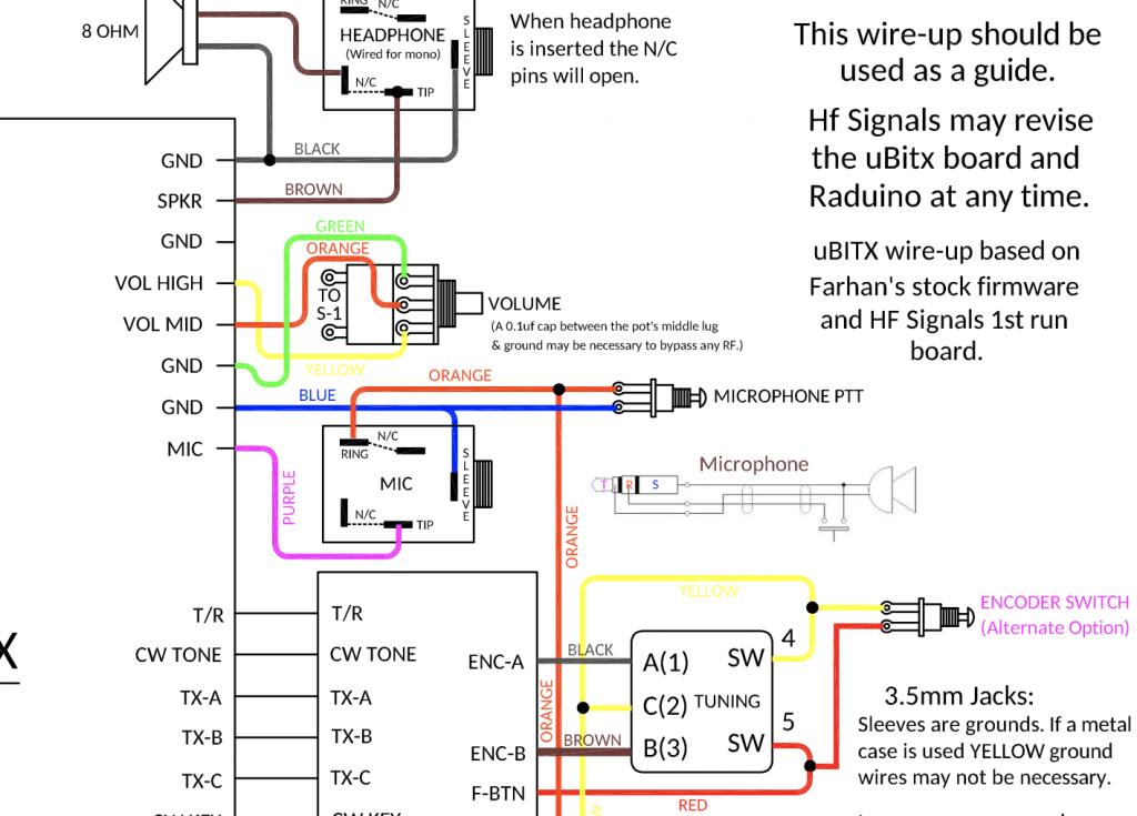
He also hacked the USB sound card so he could wire it directly to the corresponding MIC and SPKR wiring (used an old PC CD-ROM audio cable). He is using the latest firmware KD8CEC in the ubitx and now has CAT control and sound over a single USB cable to his PC/laptop. We also provide images such as wiring diagrams, engine diagrams, parts diagrams, transmission diagrams, replacement parts, electrical diagrams, repair manuals, engine schemes, wiring harness, fuse boxes, vacuum diagrams, timing belts, timing chains, brakes diagrams, and engine problems, you can find it in the search box above the right side of.
Mic wire up for ubitx (schematron.orgrradio) However the nice thing with ubitx is that you can change the default behavior by changing the firmware and upload it to the arduino. points 6 months ago.
Yes the connecting PTT to ground makes it transmit. It’s not completely clear from the wiring diagram but I can assure you that’s how it.
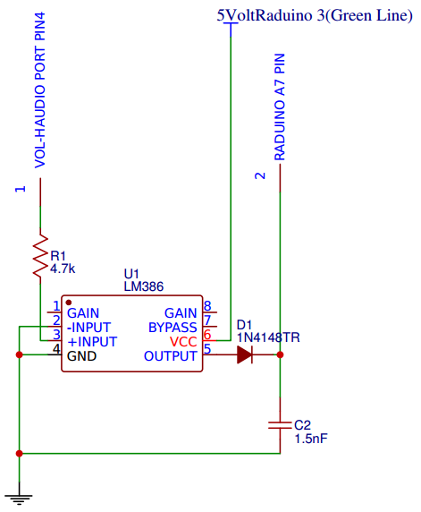
Step Wiring up the CW Key. The CW key needs a pull-up resistor of K from 5 volts to the key socket’s tip.
The green wire from the digital connector carries 5v. The blue wire of the digital connector is the keyer line (A6 of Raduino). Solder the digital connector’s blue wire to the tip tab of the CW key socket.µBITX – Wire up – HF SIGNALSµBITX – Wire up – HF SIGNALS
