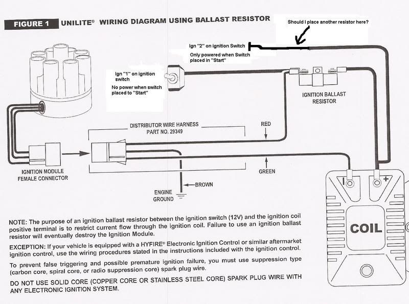
Mallory Unilite Distributor, Mallory Unilite Module Wiring Diagram, Mallory Unilite Problems, Mallory Unilite Installation, Mallory Electronic. Mallory Unilite Distributor Wiring Diagram Distributor Wiring Diagram for House Wiring Diagram Symbols • Wiring a residence or possibly.
mallory wiring diagram simple wiring diagram rh myignition co uk mallory comp unilite breakerless ignition wiring diagram Mallory Ignition. Mallory ignition wiring diagram chevy mallory ignition wiring diagram mallory unilite coils mallory unilite installation mallory ignition wiring.
the original ignition ballast resistor allows for easy conversion back to standard ignition. FIGURE 3. WIRING DIAGRAMS USING AFTERMARKET ELECTRONIC .Mallory Unilite Wiring Diagram On this website we recommend many designs about Mallory Unilite Wiring Diagram that we have collected from various sites of Wiring Diagram Collection, and of course what we recommend is the most excellent of design for Mallory Unilite Wiring Diagram.
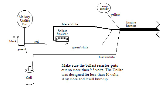
How do I wire my Mallory Distributor? Whether you have the Mallory Unalite or Dual Point with or without our Power amplifier you will find below a wiring diagram to suit and also the original instructions that come with the Mallory distributors.
May 24, · wiring diagram for mallory schematron.org need some help here, got one of those chebby engines with a mallory unilite ingition dist. in it and have no wiring set up have a resistor for the 12 in but have an extra brown wire with an eyelet on it where does this one go?
need to make this thing run on the stand, so I can sell it. thanks.
figure 2 unilite® wiring diagram using oem primary resistance wire coil ignition module female connector engine ground all other wires originally connected to the coil (+) terminal 12v/ignition switch. COIL FIGURE 2 UNILITE® WIRING DIAGRAM USING OEM PRIMARY RESISTANCE WIRE NOTE: The purpose of resistance wire between the ignition switch (12V) and the ignition coil positive terminal is to restrict current flow through the ignition coil.Another Ballast Resistor Question – CorvetteForum – Chevrolet Corvette Forum Discussionwiring diagram for mallory schematron.org – Hot Rod Forum : Hotrodders Bulletin Board
