
In today’s world, where technology plays an integral role in our daily lives, USB-C cables have become a common sight. From charging our smartphones to transferring data between devices, these cables have revolutionized the way we connect and communicate. But have you ever wondered what lies beneath the sleek exterior of a USB-C cable?
The USB-C cable schematic is a blueprint that reveals the inner workings of this versatile connector. It outlines the various components and connections that make up the cable, enabling it to provide fast charging and data transfer capabilities. Understanding the schematic of a USB-C cable is crucial for engineers and tech enthusiasts who aim to design and develop their own USB-C devices.
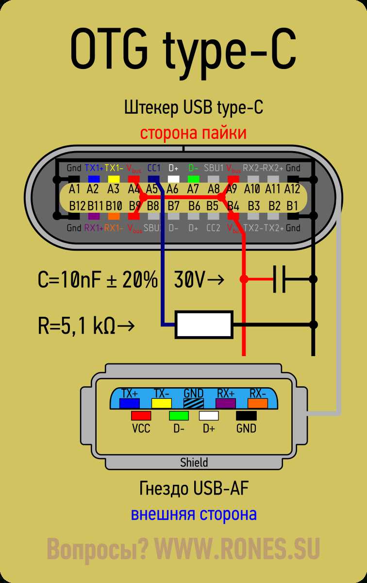
At the heart of a USB-C cable schematic is the Type-C connector. This compact and reversible connector has transformed the way we connect devices. It features 24 pins that facilitate power delivery, data transfer, and video output. The intricate arrangement of pins within the connector is depicted in the schematic, showcasing the precise positioning and purpose of each pin.
Additionally, the USB-C cable schematic illustrates the use of electronic components such as resistors, capacitors, and diodes that are strategically placed to ensure optimal signal integrity and power delivery. These components play a crucial role in maintaining the performance and reliability of the cable, mitigating issues such as voltage drop and signal interference.
In conclusion, the USB-C cable schematic is a visual representation of the inner workings of this groundbreaking connector. By understanding the schematic, engineers and enthusiasts can delve into the intricacies of USB-C technology, unlocking new possibilities for innovation and ensuring the efficient and reliable performance of future USB-C devices.
What is a USB C cable schematic?
A USB C cable schematic is a diagram or representation of the internal structure and wiring of a USB C cable. It provides a visual guide to help understand how the different components and connections are arranged within the cable.
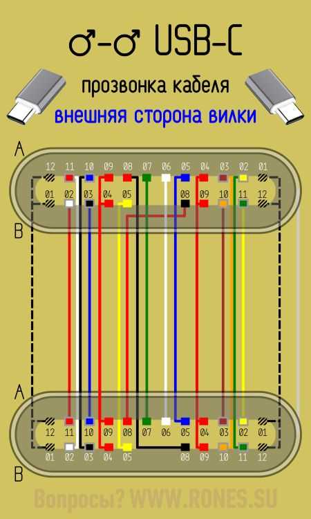
The USB C cable schematic typically includes information about the wire color coding, pin assignments, and connector orientation. It shows the arrangement of the power, ground, and data lines, as well as any additional features such as shielding or resistors.
In a USB C cable schematic, the individual wires inside the cable are usually represented by lines or color-coded symbols, indicating their function and connection points. The schematic may also include labels or annotations to provide additional information or clarify the purpose of certain components or connections.
Having a USB C cable schematic can be useful for various purposes. It can be used by engineers and technicians during the design and development of USB C cables to ensure proper wiring and functionality. It can also be helpful for troubleshooting and repairing USB C cables, as it allows for easy identification of faulty or damaged components.
In summary, a USB C cable schematic is a visual representation of the internal structure and wiring of a USB C cable. It provides valuable information about the different components, connections, and functions of the cable, making it a useful tool for design, troubleshooting, and repair.
Understanding the basics of USB C cables
USB C cables have become increasingly popular in recent years due to their versatility and convenience. These cables are used for charging and data transfer between devices, and they offer several advantages over traditional USB cables.
One of the key features of USB C cables is their reversible connector. Unlike older USB cables, which could only be inserted one way, USB C cables can be plugged in either way, making them much more user-friendly. This eliminates the frustration of trying to plug in a cable the wrong way and ensures a quick and easy connection every time.
USB C cables also support faster data transfer speeds compared to previous USB versions. With USB C, data can be transferred at speeds up to 10 gigabits per second, which is significantly faster than the 480 megabits per second offered by USB 2.0. This means that files can be transferred more quickly between devices, saving time and enhancing productivity.
The USB C cable schematic
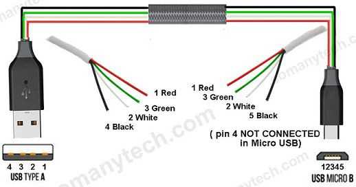
The USB C cable schematic consists of several components that enable its functionality. At the core of the cable is a set of wires that transmit power and data. These wires are sheathed in an outer layer of insulation to protect them and prevent interference from outside signals.
In addition to the wires, the USB C cable also contains a set of pins that connect to the corresponding pins in the USB C port of a device. These pins allow for the transmission of power and data between devices. The USB C cable also includes a resistor that helps regulate the power and ensure compatibility between devices.
Overall, understanding the basics of USB C cables can help users better utilize the benefits of this technology. With their reversible connector and faster data transfer speeds, USB C cables offer a convenient and efficient solution for charging and data transfer between devices.
Components of a USB C cable schematic
A USB C cable schematic consists of several components that work together to enable the transfer of data and power between devices. These components include:
- USB Type-C Connector: The USB Type-C connector is the physical interface that connects the cable to the devices. It is a reversible connector, meaning that it can be plugged in either way, eliminating the frustration of trying to insert it correctly. The connector has 24 pins that provide various functionalities such as data transfer, power delivery, and video output.
- Data Lines: The USB C cable schematic includes data lines that transmit data between devices. These data lines are typically made up of twisted pairs of wires, which help minimize interference and maintain signal integrity. The USB C cable supports various data transfer protocols, including USB 2.0, USB 3.0, USB 3.1, and USB 4.0, allowing for high-speed data transfer.
- Power Lines: USB C cables also include power lines that provide power delivery to devices. The power lines can carry both power and data simultaneously, making it possible to charge devices while transferring data. USB C cables can deliver up to 100 watts of power, enabling fast charging for smartphones, tablets, laptops, and other devices.
- EMI Shielding: To minimize electromagnetic interference (EMI), USB C cables often include EMI shielding. This shielding helps prevent interference from nearby electronic devices and ensures reliable data transfer. It is typically made of a conductive material such as aluminum or copper.
- Resistors: USB C cables may also include resistors, which are used to enable various functionalities of the cable. For example, pull-up resistors are used to detect the presence of a USB device and determine its power requirements. Different resistors values can indicate whether a device is a charger or a power source, allowing for proper power negotiation.
Overall, the USB C cable schematic is a complex design that incorporates these components to enable fast data transfer, power delivery, and versatile connectivity.
How does a USB C cable schematic work?
A USB C cable is a versatile and powerful connector that is used to connect various devices such as smartphones, laptops, tablets, and more. It is designed to provide faster data transfer speeds and higher power delivery compared to its predecessors, such as USB 2.0 and USB 3.0. The USB C cable schematic plays a crucial role in ensuring the proper functioning of these cables.
The USB C cable schematic consists of several components that work together to enable the transmission of data and power between devices. One of the key components is the Type-C connector, which is a reversible connector that can be plugged into the device in any orientation. This makes it more convenient and user-friendly compared to the older USB connectors.
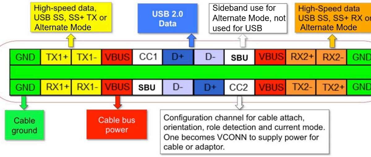
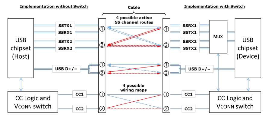
Inside the USB C cable, there are multiple wires or conductors that carry different signals. These include the VBUS (power), GND (ground), D+ and D- (data), and CC (configuration channel) wires. The VBUS wire carries power from the source device to the recipient device, while the GND wire provides a path for the return current. The D+ and D- wires enable the transmission of data between the devices. The CC wire is responsible for the identification and negotiation of power delivery capabilities between the devices.
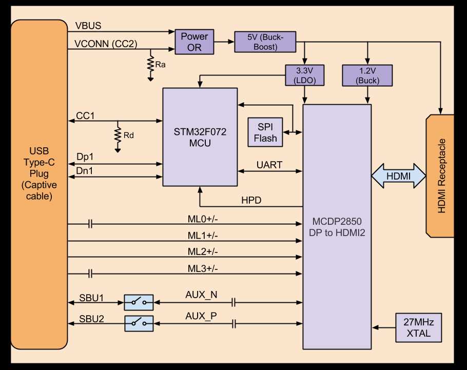
In addition to the wires, the USB C cable schematic also includes various resistors and capacitors. These components play a crucial role in ensuring proper signal transmission, power delivery, and device identification. For example, the pull-up and pull-down resistors connected to the CC wire help the connected devices negotiate power delivery capabilities. The capacitors help filter out noise and stabilize the power supply.
Overall, the USB C cable schematic is a complex arrangement of wires, resistors, capacitors, and other components that enable the reliable and efficient transmission of data and power between devices. It is designed to support high-speed data transfer and power delivery, making it an essential component in modern electronic devices.
Common Issues with USB C Cable Schematics
USB-C cables have become increasingly popular due to their versatility and ability to support high-speed data transfer and charging. However, there are some common issues that can arise with USB-C cable schematics.
1. Incorrect Pin Assignments: One of the common issues with USB-C cable schematics is incorrect pin assignments. USB-C cables have different pins for power, data transfer, and other functionalities. If these pins are not assigned correctly in the cable schematic, it can lead to issues such as slow data transfer or charging problems.
2. Lack of E-Marker Implementation: USB-C cables often include an electronic marker (E-Marker) chip that communicates with the connected devices to negotiate power delivery and other functionalities. If the cable schematic does not include the proper implementation of the E-Marker chip, it can result in compatibility issues and unreliable charging or data transfer.
3. Insufficient Power Delivery: USB-C cables are capable of delivering higher power levels compared to previous USB standards. However, if the cable schematic does not account for proper power delivery capabilities, it can lead to underpowered or slow charging. This issue is especially critical for devices that require high power, such as laptops or fast-charging smartphones.
4. Inadequate Shielding: USB-C cables need to be adequately shielded to reduce electromagnetic interference and ensure reliable data transfer. If the cable schematic does not include sufficient shielding, it can result in data loss, signal degradation, or intermittent connectivity issues.
5. Non-Compliance with USB-C Specifications: USB-C cables need to comply with specific standards and specifications to ensure interoperability and safe usage. If the cable schematic deviates from these specifications, it can lead to compatibility issues, device damage, or even safety hazards.
Overall, proper design and implementation of USB-C cable schematics are crucial to ensure optimal performance, compatibility, and safety. Manufacturers and designers need to pay attention to these common issues and adhere to the USB-C standards to deliver reliable and efficient USB-C cables.
Importance of using a correct USB C cable schematic
When it comes to USB C cables, using a correct cable schematic is of utmost importance. A USB C cable schematic refers to the specific design and arrangement of the internal components of the cable. It determines how the cable interacts with devices, how it handles power delivery, and how it transfers data.
Why is using a correct USB C cable schematic important?
- Compatibility: Using a correct USB C cable schematic ensures compatibility with various devices. Since USB C is a universal standard, it is crucial to use cables that adhere to the proper specifications. Without a correct schematic, the cable may not work with certain devices, causing inconvenience and potential damage.
- Safety: A correct USB C cable schematic ensures the safe transfer of power and data. USB C cables are capable of delivering much higher power compared to previous USB standards. Using an incorrect schematic may result in excessive power delivery, leading to overheating, device damage, or even electrical hazards.
- Efficiency: The right USB C cable schematic enables efficient data transfer and charging. By following the correct design principles, the cable can minimize signal loss, voltage drops, and other potential issues that may affect charging speed or data transfer rates.
In conclusion, using a correct USB C cable schematic is crucial for ensuring compatibility, safety, and efficiency in the use of USB C cables. It is important to verify the schematic of a cable before purchasing or using it to avoid any potential issues and optimize the overall user experience.