
A USB port, or Universal Serial Bus port, is a common interface found on computers and electronic devices that allows for the connection of various peripherals. It serves as a standardized connection point for devices such as keyboards, mice, printers, and external storage devices, among others.
The USB port pin diagram outlines the different pins or connectors found within a USB port. It is essential to understand this diagram to correctly connect and use USB devices. The pin diagram typically illustrates the various data and power pins, along with ground connections and other necessary pins.
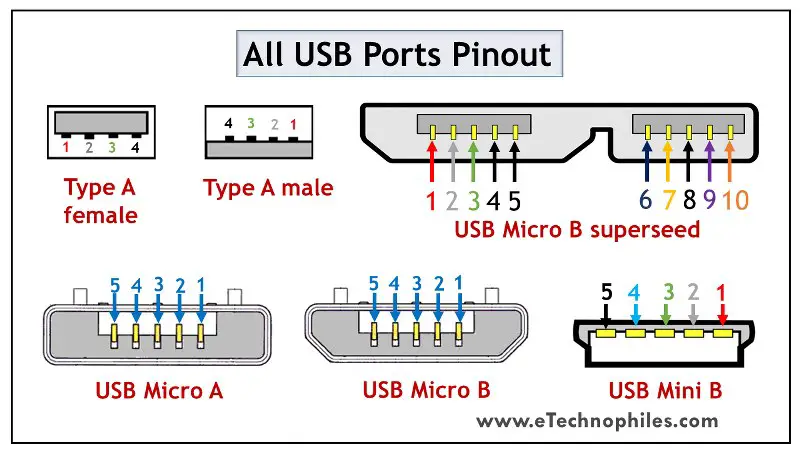
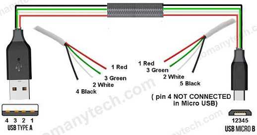
There are different types of USB ports, including USB Type-A, USB Type-B, USB Type-C, and micro USB. Each type has a specific pin diagram that varies slightly. However, there are common pins that can be found on most USB ports, including power and data pins.
Understanding the USB port pin diagram allows users to troubleshoot connection issues, correctly connect devices, and even create custom USB cables or adapters. It is a valuable resource for anyone looking to utilize the full potential of their USB ports.
Understanding the USB Port Pin Diagram
USB (Universal Serial Bus) is a widely used interface for connecting various devices to a computer. It allows for easy and fast data transfer between devices, such as keyboards, mice, printers, and external storage devices. In order to understand how a USB port works, it is important to familiarize oneself with the USB port pin diagram.
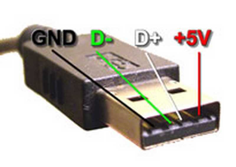
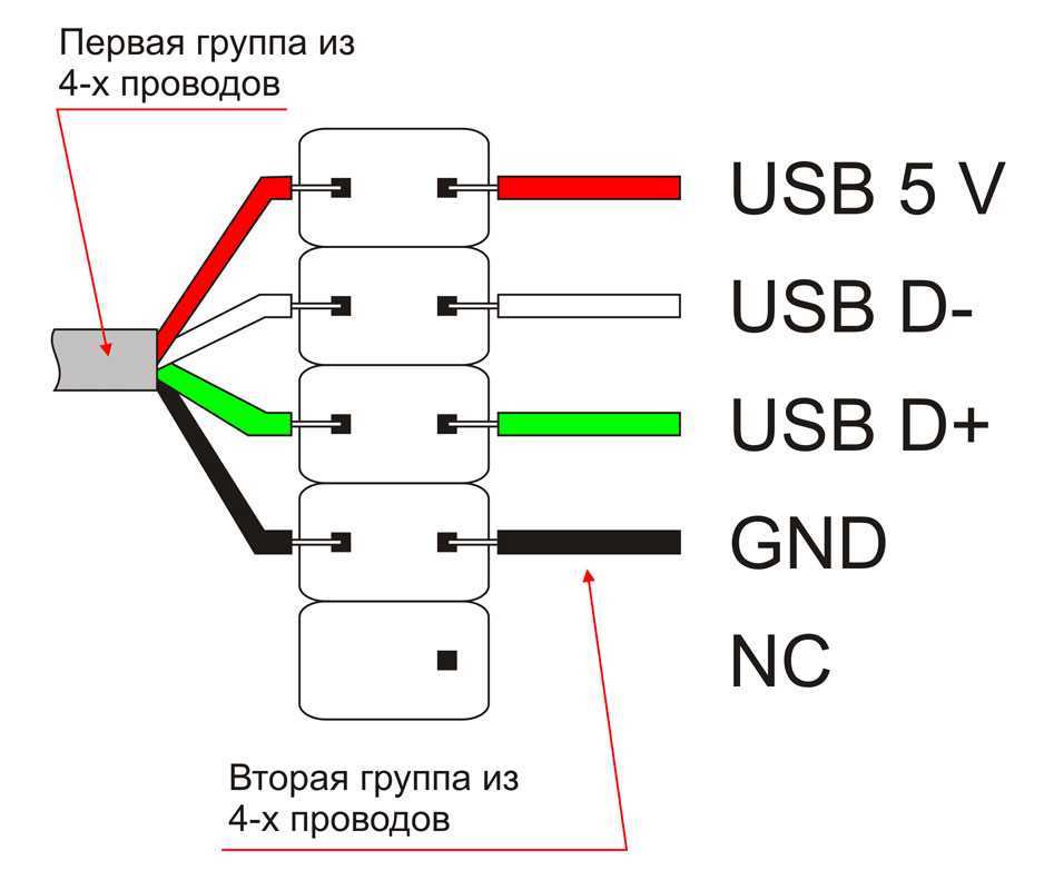
The USB port pin diagram consists of multiple pins that serve different functions. The most common type of USB port is the USB Type-A port, which is typically found on computers and other electronic devices. This type of port has four pins: Vcc, D-, D+, and Ground.
- Vcc: This is the power supply pin, which supplies power to the connected device.
- D- and D+: These are the data pins, which are used for transmitting data between the computer and the connected device.
- Ground: This is the ground pin, which completes the electrical circuit.
It is important to note that there are also other types of USB ports, such as USB Type-B and USB Type-C ports, which have different pin configurations. For example, USB Type-C ports have more pins and support additional features, such as faster data transfer speeds and the ability to carry video signals.
Understanding the USB port pin diagram is essential for properly connecting devices to a computer. It allows users to identify the correct pins for power supply and data transfer, ensuring that the connected devices function properly. Additionally, knowing the pin diagram can help troubleshoot connectivity issues and ensure compatibility between devices and USB ports.
Overview of USB Port
USB (Universal Serial Bus) is a widely used interface that allows electronic devices to connect and communicate with each other. USB ports are found on almost every computer and many other devices, such as smartphones, tablets, and gaming consoles. The USB port serves as a gateway for transferring data, supplying power, and connecting peripheral devices.
A USB port is composed of several pins, each serving a specific purpose. The standard USB port has four pins: VCC (power supply), D- (data line), D+ (data line), and GND (ground). The VCC pin provides power to the connected device, while the D- and D+ pins are used for data transmission. The GND pin ensures a common reference point for electrical signals.
The USB protocol supports various data transfer speeds, ranging from USB 1.0 with a maximum speed of 12 Mbps to USB 3.1 Gen 2 with a speed of up to 10 Gbps. USB devices are backward compatible, meaning that newer devices can still be connected to older USB ports, albeit at lower speeds.
USB ports have evolved over the years, with newer versions introducing additional features and improvements. USB 3.0, for example, introduced a new set of pins for faster data transmission, while USB Type-C introduced a reversible connector that can be plugged in either way.
- VCC (Power Supply): Supplies power to the connected device.
- D- (Data Line): Used for transmitting data.
- D+ (Data Line): Used for transmitting data.
- GND (Ground): Provides a common reference point for electrical signals.
In conclusion, USB ports are an essential component of modern electronic devices, providing a versatile and standardized interface for data transfer and power supply. The various pins of a USB port enable efficient communication between devices, facilitating the seamless integration of peripherals and accessories.
Understanding USB Pin Diagram
USB (Universal Serial Bus) is a widely used connector standard for connecting various devices to a computer or other electronic devices. It provides a standardized and convenient interface for data transfer and power supply.
The USB connector typically has four pins, each serving a specific purpose. These pins are labeled as VCC, D-, D+, and GND. Understanding the pin diagram is essential for proper connection and functioning of USB devices.
VCC: The VCC pin (also known as +5V) provides power to the connected device. It typically supplies a voltage of 5 volts. This pin is connected to the power source, such as a USB port on a computer or a USB charger.
D- and D+: The D- and D+ pins are responsible for data transfer between the USB device and the host device, such as a computer. These pins carry differential signals and are used for bidirectional data transmission. The data transfer rates depend on the USB version and device capabilities.
GND: The GND pin (also known as ground) serves as the reference voltage for the USB connection. It is connected to the common ground of both the USB device and the host device to ensure proper electrical grounding.
It is important to note that there are different types of USB connectors, such as USB Type-A, USB Type-B, USB Type-C, and mini/micro USB. Each type of connector may have additional pins or different pin configurations, but the basic functionality and purpose of the pins remain the same.
Understanding the USB pin diagram is crucial when connecting USB devices and troubleshooting connection issues. It ensures proper power supply and data transfer, allowing devices to communicate effectively and function as intended.
Power Supply Pins
The USB port pin diagram consists of several pins, including power supply pins. These pins are responsible for providing power to connected devices. There are two power supply pins in a USB port, namely VBUS (Voltage Bus) and GND (Ground) pins.
The VBUS pin, also known as the +5V pin, is responsible for supplying a regulated 5V DC power to the connected devices. This pin is used to power up USB devices such as flash drives, keyboards, and mice. It is important to note that the maximum current that can be drawn from the VBUS pin is 500mA, unless the USB device supports a higher current mode such as USB 3.0 or 3.1.
The GND pin is connected to the ground reference of the power supply system. It is responsible for completing the electrical circuit and providing a return path for the current flowing through the VBUS pin. The GND pin ensures that the voltage between the VBUS pin and the GND pin is maintained at a stable level.
Both the VBUS and GND pins are crucial for the proper functioning of USB devices. Without a proper power supply, the connected devices may not function correctly or fail to operate altogether. Therefore, it is important to ensure that these power supply pins are properly connected and provide a stable power source.
Data Transfer Pins
The USB port consists of several pins that are responsible for different functions, including data transfer. These pins enable the communication between the USB device and the host device, allowing for the exchange of data and information.
One of the key data transfer pins in a USB port is the D+ and D- pair. These pins are responsible for carrying the actual data signals between the devices. The D+ pin represents the positive data signal, while the D- pin represents the negative data signal. These pins work together to transmit the binary data from one device to another.
Another important data transfer pin is the VBUS pin. This pin is responsible for providing power to the USB device. It carries the power signal, allowing the USB device to receive power from the host device. The VBUS pin is crucial for the data transfer process, as it ensures that the USB device has enough power to operate and transfer data effectively.
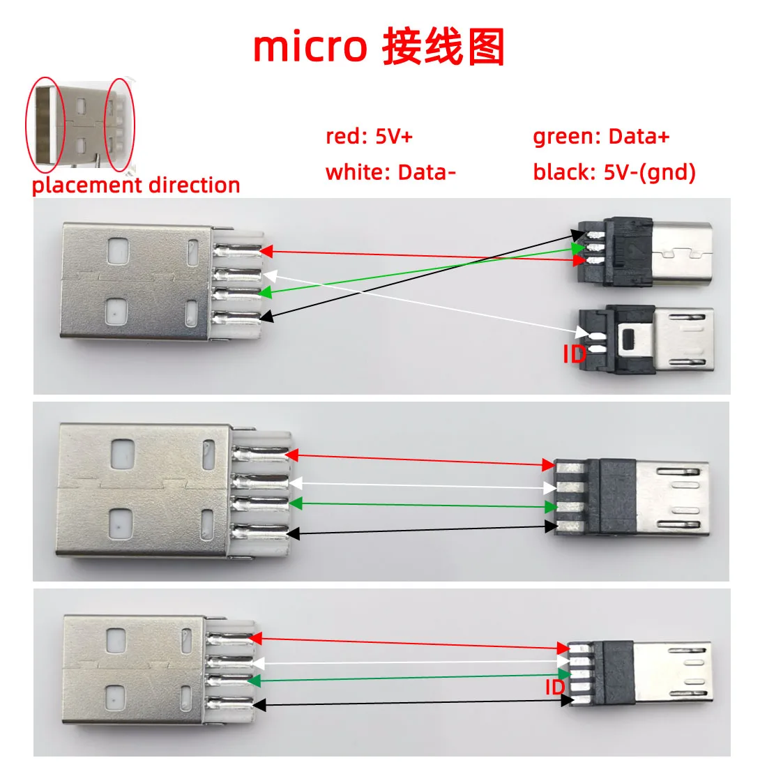
In addition to the D+, D-, and VBUS pins, there are also other pins involved in data transfer, such as the GND (ground) pin, which provides a reference voltage for the data signals, and the ID pin, which is used for device identification purposes. These pins, along with the data transfer pins, work together to establish a connection and facilitate the transfer of data between the USB device and the host device.
Overall, the data transfer pins in a USB port play a crucial role in enabling the exchange of data and information between devices. These pins, including the D+, D-, VBUS, GND, and ID pins, work together to establish a reliable and efficient connection, allowing for seamless data transfer in USB devices.
Ground Pins
One of the essential components in a USB port is the ground pin. The ground pin is responsible for providing a reference voltage for the data and power signals transmitted through the port. It acts as a common reference point for all the signals and helps to maintain stability and reliability in the USB communication. The ground pin is usually connected to the ground plane of the device or the system to ensure proper grounding and prevent any interference or noise in the signal transmission.
In a USB port, there are typically multiple ground pins. These pins are usually labeled as GND or ground, and they are interconnected internally. The presence of multiple ground pins helps to ensure a low impedance path for the return current and minimizes the chances of signal interference or noise. It also facilitates proper distribution of the ground potential throughout the USB system, enabling efficient communication between devices.
Other Pins and Functions
The USB port also includes several other pins and functions, which can provide additional capabilities and functionality. Some of the most common additional pins and functions include:
- Vcc: This pin provides the voltage supply for the USB port. It is typically connected to the power supply of the system and provides power to the connected USB devices.
- GND: This pin is the ground reference for the USB port. It is connected to the ground of the system and provides a common ground for the USB devices.
- VBUS: This pin is used to detect the presence of a power source. It is typically connected to a power switch or a USB charging controller and allows the system to detect when a USB device is connected.
- D+ and D-: These differential data lines are used for data transmission between the USB host and the USB device. The D+ and D- signals are used to transmit and receive data in a balanced manner, ensuring reliable data transfer.
- ID: This pin is used for identification and configuration purposes in USB OTG (On-The-Go) applications. It allows a device to determine whether it is acting as a host or a peripheral and to switch between the two roles dynamically.
- Shield: This pin is used for shielding and grounding purposes. It provides additional protection against electromagnetic interference and helps to maintain a reliable connection.
These additional pins and functions ensure proper power supply, data transmission, identification, and protection in USB systems. They play a crucial role in enabling the functionality and versatility of USB ports.
Overall, understanding the pinout and functions of USB ports can help in troubleshooting issues, designing custom USB cables or connectors, and developing USB-enabled devices.