MANROSE SHOWER LIGHT & EXTRACTOR FAN KIT CHROME 100MM – Screwfix
First, click the device or connection name on the left of the dialog, then double- check the manufacturer name on the Interpretation of the Diagrams and Examples. SmartSound: Background Music Made to Measure. (if the player’s timecode is being used; may include a selected shift, page ). TC data is trans-.
of the wiring is to be accomplished under the direction of the facilities engineer. In ad- dition, listed The UniStat (USIX) status indicator contains one base, sleeve, PCB, color LED array, lens, cap, and .

PCB, USIXTC. K USISTC.
UniStat®, tri-color, sounder, single-high, VAC. USIXQC. UniStat®, quad-color, hazardous location, single-high, 24VDC.

USIXTC. A power-on-reset (POR) circuit is used to eliminate power-supply .
TYPICAL SYSTEM BLOCK DIAGRAM OTW System Microcontroller SD I2C .. 20 30 40 50 60 70 80 90 TC – Case Temperature – °C Figure 6.
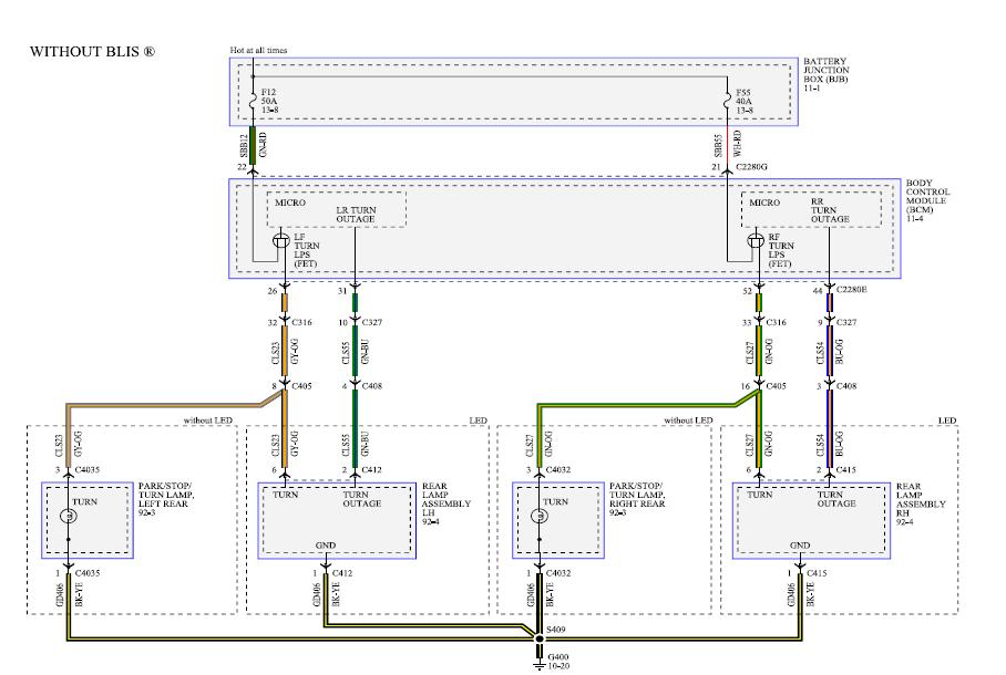
.. of high-level music transients and extreme speaker load impedance drops. USITC, UniStat, tri-color, single-high, VAC, USISQC, UniStat, quad-color, sounder, single-high, 24VDC, USISTC.FEDERAL SIGNAL CORPORATION MicroStat ® Status Indicator Model MSL COMPACT STATUS INDICATOR IN WATER-TIGHT ENCLOSURE • MSL1, MSL2, MSL3 available in 24VAC/DC, VAC and VAC; MSL4 and MSL5 available in 24VAC/DC and VAC • Factory assembled • Small footprint — only ” diameter ( mm) • Vibration-resistant W wedge lamp • Surface mount and .
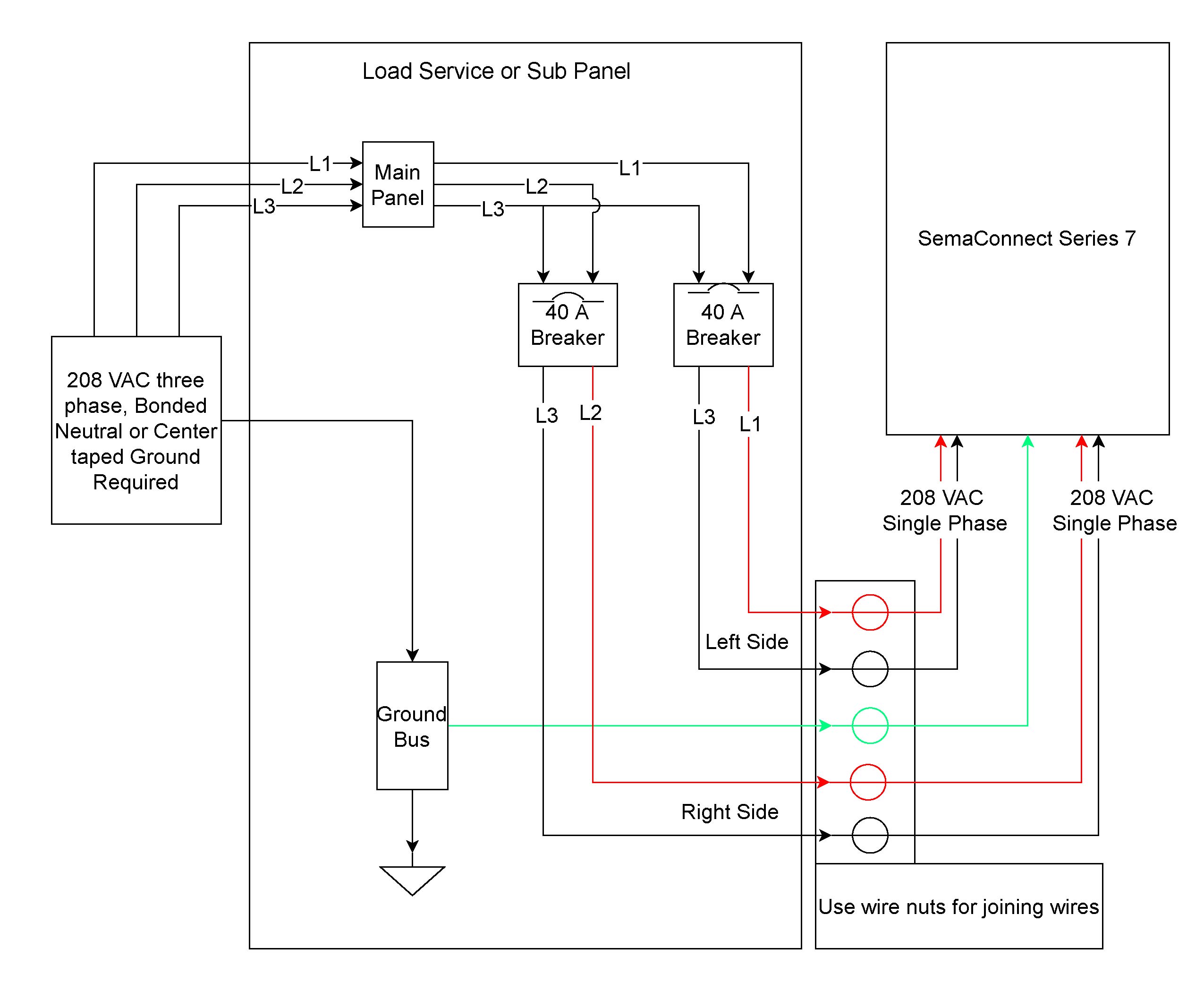
Wiring Diagram Book A1 15 B1 B2 16 18 B3 A2 B1 B3 15 Supply voltage 16 18 L M H 2 Levels B2 L1 F U 1 V F U 2 L2 L3 GND H1 H3 H2 H4 F U 3 X1A F U 4 F U 5 X2A R. Easy to Understand and Fully Illustrated Wiring Diagrams for Home Electrical Projects Including 3 way switches, 4 way switches, outlets, switched outlets, ranges, dryers, smoke detectors, ceiling fans, exhaust fans, home wiring and many more with articles and pictures. 1 WIRING DIAGRAM BY MODEL This document describes car models to which the AFC neo (Product code: A) is applicable, and ECU terminal arrangement drawings.
Please login to continue Please login to continue.IC datasheet pdf-TASA,pdf( W STEREO DIGITAL AMPLIFIER POWER STAGE)_图文_百度文库Electrical Wiring Diagrams for Air Conditioning Systems – Part Two ~ Electrical Knowhow