USOC RJ14 or RJ14C – Two pairs of wires in a 4, 6, or 8 position modular jack. Pair 1 would be the two center pins, pair 2 on the next two pins. USOC RJ14 or RJ14C – Two pairs of wires in a 4, 6, or 8 position modular jack. Pair 1 would be the two center pins, pair 2 on the next two pins.
TA and TB are the two color codes used for wiring eight-position RJ45 backward compatibility to both one pair and two pair USOC wiring schemes. Figure 1 is the wiring scheme for the plug side of an RJ connector. The diagram is shown with the “hook clip” on the underside.
The typical RJ connector. TA and TB are the two color codes used for wiring eight-position RJ45 backward compatibility to both one pair and two pair USOC wiring schemes.The first revision of the standard, TIA/EIAA was released in The standard was updated to revision B in The demands placed upon commercial wiring systems increased dramatically over this period due to the adoption of personal computers and data communication networks and advances in those.
Common Wiring Configurations: USOC RJ11 or RJ11C – One pair of wires (pair 1) in a 4, 6, or 8 position modular jack. Yes, the 4 position modular plug will plug into the 6 position and 8 position modular jack, and the 6 position modular plug will plug into the 8 position modular jack.
USOC NOTES RJ (Registered Jack) numbers end with a letter designating wiring or mounting arrangement. The Letter “C” in the USOC indicates the jack is baseboard or flush mounted for a desk type unit.
“W” indicates the jack is for a wall mounted unit. “M” is for multiple mounting arrangements.
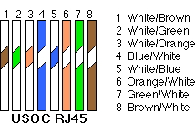
“X” is a single series connection. Figure 2 is the wiring scheme for the plug side of an RJ connector in accordance with TB standards.
The TB standard is the most commonly used. The wiring diagram is shown with the “hook clip” on the underside.
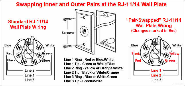
) USOC isn’t commonly used anymore but is the type of wiring scheme telephones use. It would make sense to wire ports following the USOC specification but by using TA a cable can later be easily switched from voice to data or vice versa in the future.Usoc Wiring Pin Diagram | Wiring LibraryStandard EIA /TIA A EIA /TIA B, USOC, RJ45 Pinout Wiring Diagram
