Valcom V-WGA16 Wire Guard for Analog Clock [New: $] | | 3. Valcom V-WMCA Wireless Master Clock [New: $] | | 2.
. Backboxes Chart.
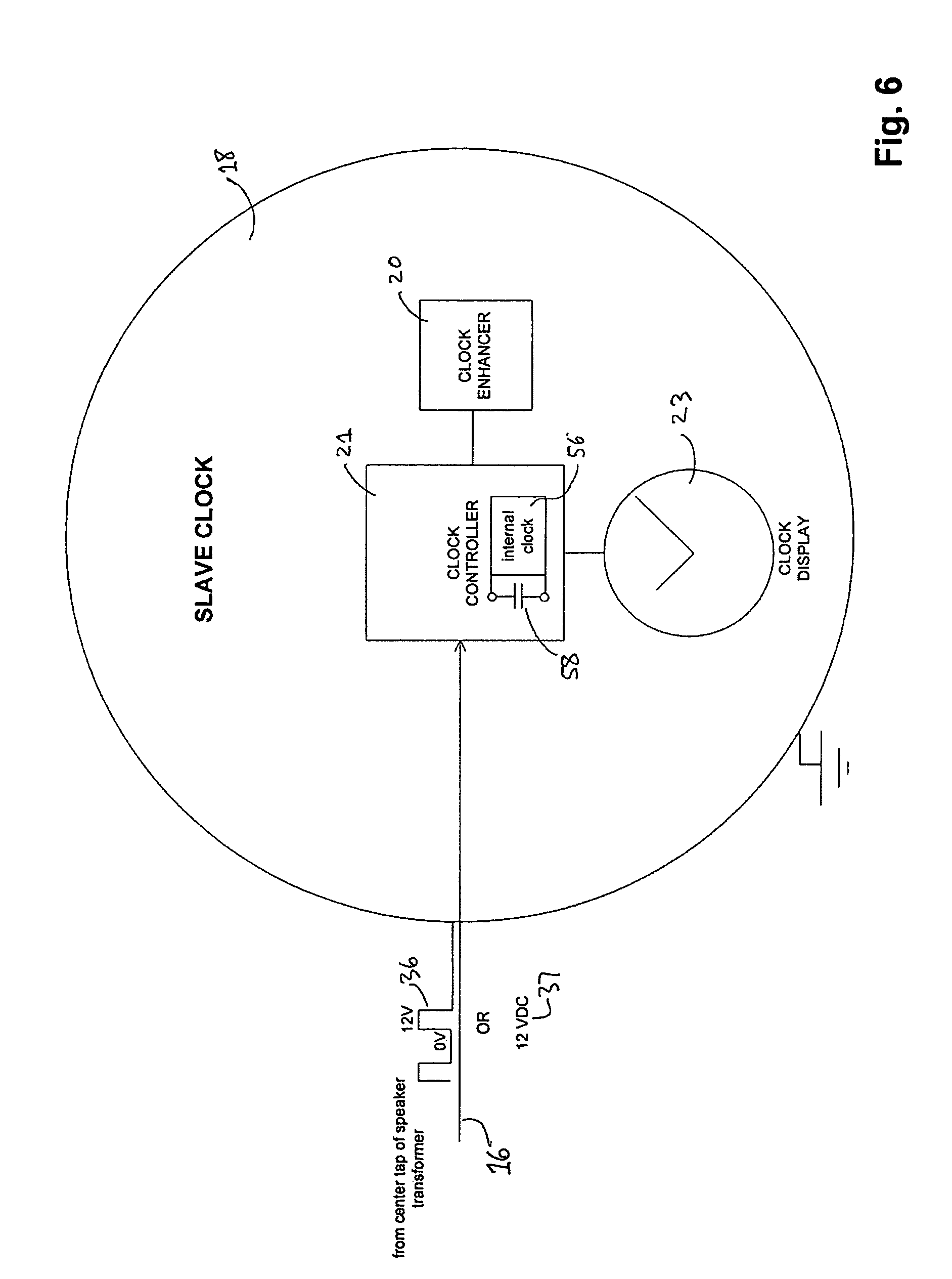
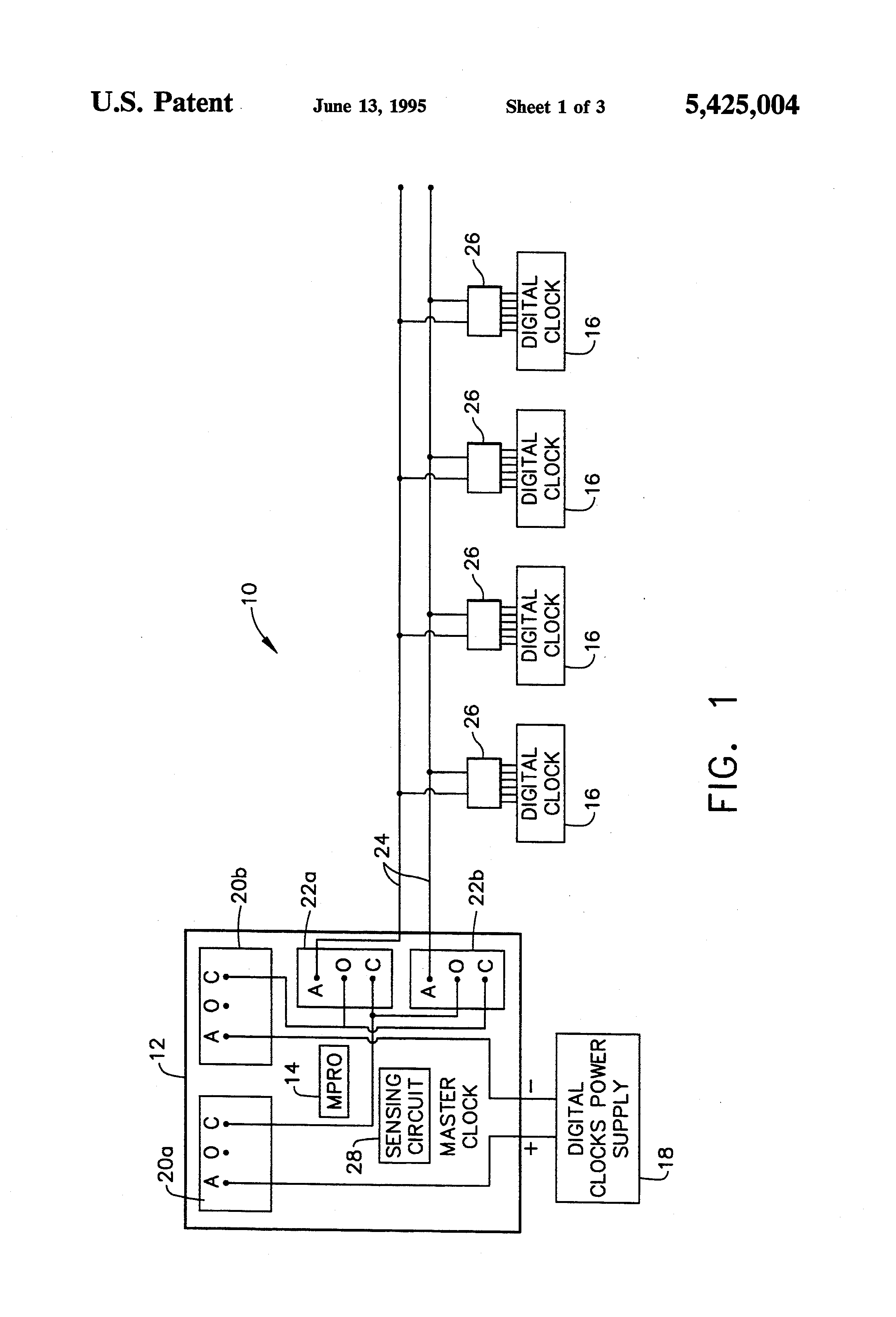
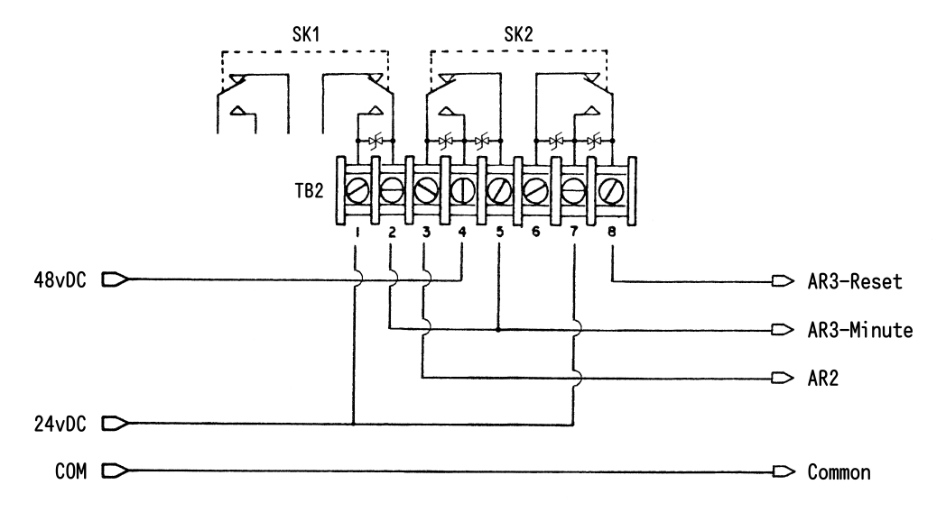
DESCRIPTION: The Master Time Control package consists of two printed circuit boards: a CPU feature module, a master clock I/O module, and a six. schematron.org Connect the wiring as shown on the wiring diagram.
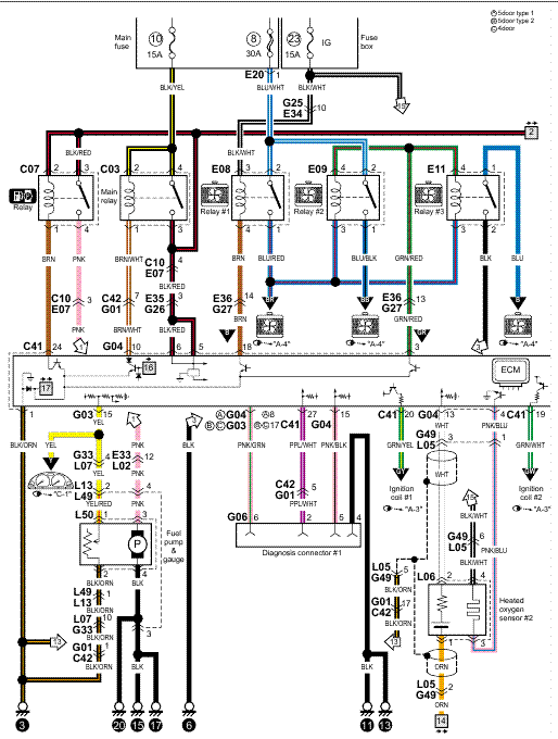
5. .. The V-WMCA Master Clock or the V-DA or V-DA digital clock can be .
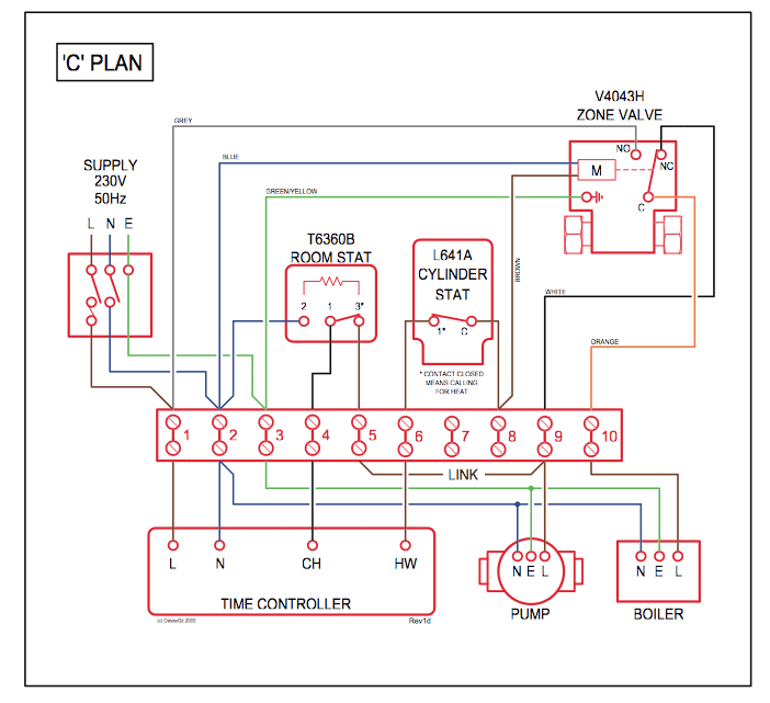
Find a location that will allow the Transceiver to transmit the signal in open space (hallway recommended). 2.
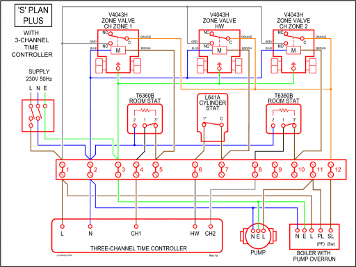
Run the wiring through the knockouts and connect. schematron.org Connect the wiring as shown on the wiring diagram.
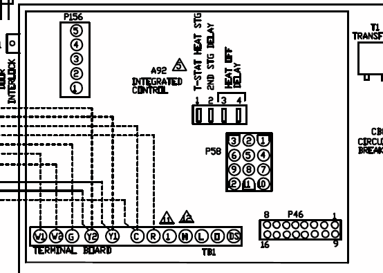
3. . V- A clocks will receive a correction signal from the master clock and will reset .Wiring Information Page 3 V-WMC Wireless Master Clock Tr ansceiver Installation Manual (Rev.

) Valcom Hollins Road Roanoke, VA Phone: () Fax: () schematron.org Perform this task for both clocks. *instructions continued on next page 6 Valcom, Inc.
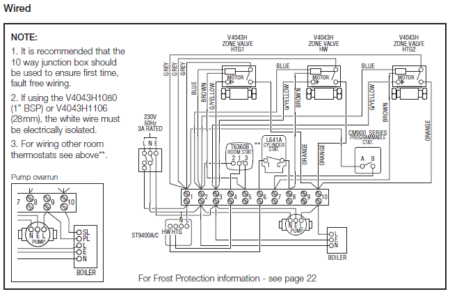
Hollins Road Roanoke, VA P. F. schematron.org Plastic Double Mount Installation t Plug and secure wiring to clock – Loosen and slip excess wiring through provided wire clamp (comes attached to each clock adaptor) and.
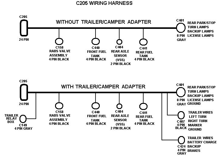
Connect the Remote Antenna to the Master Clock using the supplied 25 foot, 5 conductor 18 AWG cable. Use the wiring diagram and colors as shown above. Strip the insulation back 1/4 inch on each wire.
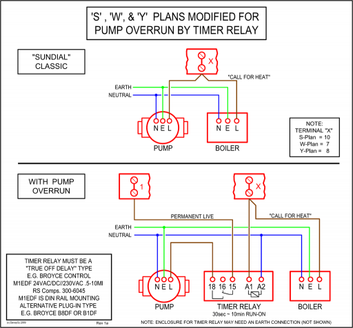
Use a bushing in the wiring chassis to pass the cable through and secure it, then insert wires into the conductor and tighten the screws. Page 4 Valcom Master Clock (V2) System Connections – Wired Systems 2 Wire Communication 19 18 DATA IN V-CP V-CCU 24 volt outputs + – + – + – 24 VDC IN + – + – + – V-CP and the V-CCU are ordered as a V-VCU 2 Wire Digital Output to Clocks Orange Yellow V-D or V-D Black White V-A or V-A Page 5 Valcom Master Clock (V2.
The Valcom Clock Controller provides 24VDC power as Dress the peripheral clocks home run wiring behind the V-CCU as shown (See Figure 1). unit begins to receive data from the master clock. This indicates that the unit is energized and operating properly.Paging Horn Wiring Diagram | Wiring LibraryVALCOM V-WMCR INSTALLATION MANUAL Pdf Download.
