
The valve timing diagram is an essential tool for understanding the operation of a 2-stroke engine. This diagram shows the precise timing of the opening and closing of the intake and exhaust ports, as well as the movement of the piston and the transfer ports. By analyzing this diagram, engineers can optimize the engine’s performance and efficiency.
During the intake stroke, the piston moves downwards, creating a vacuum that draws in the air-fuel mixture through the intake port. The intake port opens just before the piston reaches the bottom dead center (BDC), and closes shortly after the piston begins its upward stroke. This ensures that the maximum amount of fresh mixture is drawn into the cylinder.
On the compression stroke, the piston moves upwards, compressing the air-fuel mixture in the combustion chamber. The transfer ports, located in the cylinder walls, open just before the piston reaches the top dead center (TDC), allowing the compressed mixture to be transferred from the crankcase to the combustion chamber. The transfer ports then close as the piston begins its downward stroke.
During the power stroke, also known as the combustion stroke, the mixture in the combustion chamber is ignited by the spark plug. This causes a rapid expansion of gases, which pushes the piston downwards, generating power. The exhaust port, located opposite the transfer ports, opens just before TDC, allowing the burned gases to be expelled from the cylinder. The exhaust port then closes shortly after the piston begins its upward stroke.
In conclusion, the valve timing diagram of a 2-stroke engine is a crucial tool for understanding the engine’s operation and optimizing its performance. It shows the precise timing of the intake and exhaust ports, as well as the movement of the piston and the transfer ports. By studying this diagram, engineers can make informed decisions about camshaft profiles, port shapes, and other design features to improve the engine’s efficiency and power output.
Valve Timing Diagram of 2 Stroke Engine PPT
In the two-stroke engine, the valve timing diagram plays a crucial role in determining the engine’s performance. The valve timing diagram represents the opening and closing of the intake and exhaust ports in relation to the position of the piston.
The valve timing diagram for a two-stroke engine can be represented through a PowerPoint presentation (PPT) to provide a visual understanding of the process. This presentation can include various slides that illustrate the different stages of the engine’s operation, such as the intake, compression, combustion, and exhaust.
By using diagrams, animations, and text, the PPT can demonstrate how the intake port opens to allow the air-fuel mixture to enter the combustion chamber while the exhaust port opens to expel the burnt gases. The valve timing diagram also shows the overlap period when both the intake and exhaust ports are open simultaneously.
Furthermore, the PPT can highlight the importance of proper valve timing in optimizing the engine’s performance. It can explain how the timing affects the engine’s power, torque, and fuel efficiency. This information can be valuable for engine designers, mechanics, and enthusiasts who want to understand the inner workings of a two-stroke engine.
In conclusion, a Valve Timing Diagram of a 2-stroke engine presented in a PowerPoint format can provide a comprehensive visual representation of the engine’s operation. It can help in understanding the timing of the intake and exhaust ports, as well as the impact on the engine’s performance.
Overview

The Valve Timing Diagram (VTD) of a 2-stroke engine is a graphical representation of the opening and closing of the intake and exhaust valves during the engine’s operation. It helps to understand the sequence of events that occur in the engine cylinder, which is essential for optimizing performance and efficiency.
The VTD shows the relationship between the position of the piston inside the cylinder and the opening and closing of the valves. It is typically represented using a diagram with a horizontal axis representing the piston position and a vertical axis representing the degrees of crankshaft rotation.
The VTD includes the following important events:
- Intake Stroke: The intake valve opens, allowing the air-fuel mixture to enter the cylinder. This occurs when the piston is at or near the bottom dead center.
- Compression Stroke: The intake valve closes, and the piston moves upwards, compressing the air-fuel mixture. This occurs when the piston is near the top dead center.
- Combustion Stroke: The spark plug ignites the compressed air-fuel mixture, causing an explosion. This forces the piston back down, generating power. This occurs when the piston is at or near the bottom dead center.
- Exhaust Stroke: The exhaust valve opens, and the piston moves upwards, expelling the burned gases from the cylinder. This occurs when the piston is near the top dead center.
The VTD helps engineers and technicians analyze the performance of the engine and make adjustments to optimize its operation. By adjusting the timing of the intake and exhaust valves, it is possible to improve power output, reduce emissions, and maximize fuel efficiency.
Note: The information presented here is a simplified overview of the Valve Timing Diagram. The actual VTD can vary depending on the design and configuration of the specific 2-stroke engine.
Understanding Valve Timing
In an internal combustion engine, valve timing refers to the precise timing at which the intake and exhaust valves open and close in relation to the engine’s piston movement. Proper valve timing is essential for the engine to function efficiently and produce optimal power.
The valve timing diagram of a 2-stroke engine illustrates the events that occur during each stroke of the engine cycle. It shows the position and timing of the intake, compression, combustion, and exhaust phases. The diagram helps to visualize the relationship between piston and valve movement and allows engineers to optimize the engine for maximum performance.
There are several factors that affect valve timing in a 2-stroke engine. These include the rpm range, engine displacement, and desired power output. At low rpm, the intake and exhaust valves need to open and close earlier to ensure efficient air-fuel mixture intake and exhaust gas expulsion. As the engine speed increases, the valve timing needs to be adjusted to allow for better scavenging of exhaust gases, maximizing combustion efficiency.
Valve timing is typically controlled by mechanical components such as camshafts, timing belts, or chains. These components are designed to open and close the valves at the precise moments required for optimal engine performance. Advances in technology have also introduced variable valve timing systems, where the valve timing can be adjusted on the fly, optimizing performance at different engine speeds and loads.
In summary, understanding valve timing is crucial for optimizing the performance and efficiency of a 2-stroke engine. By carefully controlling when the intake and exhaust valves open and close, engineers can ensure that the engine performs optimally throughout its rpm range, maximizing power output and minimizing emissions.
Importance of Valve Timing Diagrams
A valve timing diagram is a graphical representation of the opening and closing of the intake and exhaust valves of an engine. It is an essential tool for understanding the timing and coordination of the valves, which directly affects the engine’s performance and efficiency.
The valve timing diagram provides critical information about the engine’s power output, torque characteristics, and fuel efficiency. It helps engineers and technicians optimize the engine’s performance by adjusting the timing of the valves to achieve the desired balance between power and fuel consumption.
Key factors affected by the valve timing:
- Scavenging Efficiency: The valve timing determines the degree of overlap between the intake and exhaust valves. Optimizing the overlap can improve scavenging efficiency, which ensures the removal of exhaust gases and the introduction of fresh air-fuel mixture into the cylinder.
- Power Output: The valve timing affects the amount of air-fuel mixture entering the cylinder and the exhaust gases leaving, directly influencing the engine’s power output. By adjusting the valve timing, engineers can tune the engine for better power delivery across different engine speeds.
- Torque Characteristics: The valve timing determines the timing of the intake and exhaust events, which affects the engine’s torque characteristics. By adjusting the timing, engineers can optimize torque delivery at specific RPM ranges, improving the engine’s overall drivability.
- Fuel Efficiency: Proper valve timing ensures efficient combustion by allowing optimal air-fuel mixture intake and exhaust gas evacuation. This can result in improved fuel efficiency, reducing the engine’s overall fuel consumption and environmental impact.
Valve timing diagrams are also crucial for diagnosing engine problems and troubleshooting. By analyzing the valve timing, technicians can identify issues such as valve malfunctions, incorrect camshaft timing, or valve overlap problems, allowing for timely repairs and maintenance.
In conclusion, valve timing diagrams play a vital role in understanding and optimizing the performance and efficiency of engines. They provide valuable information for tuning the engine’s power output, torque characteristics, and fuel efficiency, making them an indispensable tool for engineers and technicians.
Components of Valve Timing Diagram
The valve timing diagram is a graphical representation of the events that occur during the opening and closing of the intake and exhaust valves in a 2-stroke engine. It provides a visual depiction of the relationship between the piston position, valve position, and the timing of various events in the engine cycle.
The valve timing diagram consists of several key components:
- Piston Position: The position of the piston is represented on the diagram by a vertical line. It indicates the movement of the piston as it travels up and down in the cylinder.
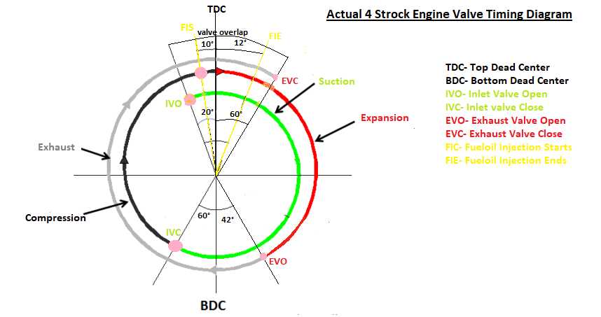
- Intake Valve Opening (IVO): This is the point at which the intake valve opens to allow the fresh air-fuel mixture into the cylinder. It is represented on the diagram by a vertical line crossing the horizontal line representing the piston position.
- Intake Valve Closing (IVC): This is the point at which the intake valve closes, sealing the cylinder and preventing any further intake of air-fuel mixture. It is represented on the diagram by a horizontal line crossing the vertical line indicating the piston position.
- Exhaust Valve Opening (EVO): This is the point at which the exhaust valve opens, allowing the burnt gases to escape from the cylinder. It is represented on the diagram by a diagonal line crossing the horizontal line representing the piston position.
- Exhaust Valve Closing (EVC): This is the point at which the exhaust valve closes, sealing the cylinder and preventing any further escape of gases. It is represented on the diagram by a diagonal line crossing the vertical line indicating the piston position.
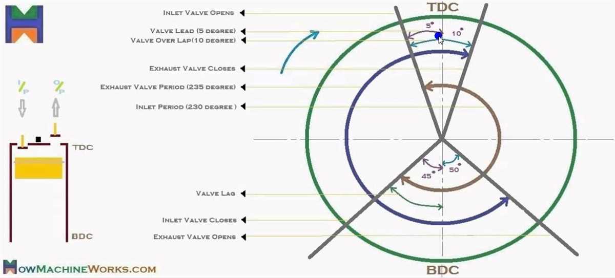
- Overlap: Overlap refers to the period of time when both the intake and exhaust valves are partially open. It allows fresh air-fuel mixture to enter the cylinder while the burnt gases are still being expelled. Overlap is represented on the diagram by the region where the vertical and diagonal lines representing the intake and exhaust valve events overlap.
The valve timing diagram provides valuable information about the engine’s performance and efficiency. By analyzing the diagram, engineers can optimize the timing of the valves to achieve the desired power output and fuel efficiency for a given engine design.
Working of Valve Timing Diagram in 2 Stroke Engine
The valve timing diagram of a 2 stroke engine plays a crucial role in determining the efficiency and performance of the engine. It shows the opening and closing of the intake and exhaust valves in relation to the movement of the piston. Here, we will discuss the working of the valve timing diagram in a 2 stroke engine.
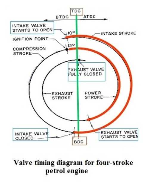
The valve timing diagram consists of two main events: the intake stroke and the exhaust stroke. During the intake stroke, the piston moves downward, creating a low-pressure area in the cylinder. This low-pressure area allows the fresh air-fuel mixture to enter the combustion chamber through the open intake port. The intake valve opens at the beginning of the intake stroke and closes before the piston reaches the bottom dead center (BDC). It is important for the intake valve to close before the piston reaches BDC to prevent the loss of the fresh charge into the exhaust port.
During the exhaust stroke, the piston moves upward, compressing the burnt gases and pushing them out through the open exhaust port. The exhaust valve opens before the piston reaches the top dead center (TDC) and closes after the piston passes TDC. This ensures the efficient expulsion of the exhaust gases from the combustion chamber. It is also important for the exhaust valve to close after the piston passes TDC to prevent the loss of fresh charge during the combustion process.
In a 2 stroke engine, the valve timing diagram is designed in such a way that the intake and exhaust events occur at specific points in the piston’s movement. This ensures proper scavenging, combustion, and expulsion of gases from the cylinder. The correct timing of the intake and exhaust valves allows for maximum power output and efficiency.
In conclusion, the valve timing diagram in a 2 stroke engine is crucial for the engine’s performance. It dictates the opening and closing of the intake and exhaust valves in relation to the movement of the piston. Proper valve timing ensures efficient scavenging, combustion, and expulsion of gases from the cylinder, resulting in optimal power output and efficiency.