
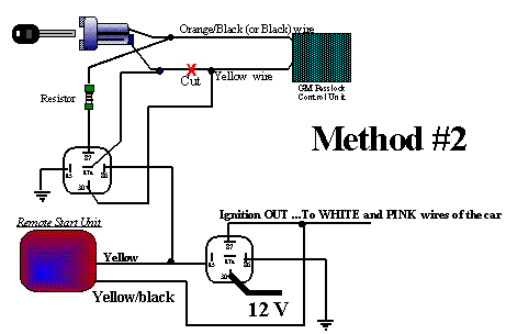
VATS (Vehicle Anti Theft System) was introduced by GM on the Corvette because the . In , GM changed the wiring on some of the VATS vehicles. Wiring Diagrams By the end of that thread I had learned about GM VATS (vehicle anti-theft system) and in particular about Passkey II.
Either add some type of connectors to you new “VATS resistor box” or just then bypass the starter relay with a ”trailer wiring connector”. you the schematic/ raddyshack parts list to do with as you please –post here, mfg,etc. This is a DIAGRAM for GM’S VATS/PASSKEY ANTI-THEFT System for the IF BYPASS MODULE.
You will ONLY need to use the wires in the. Fig.
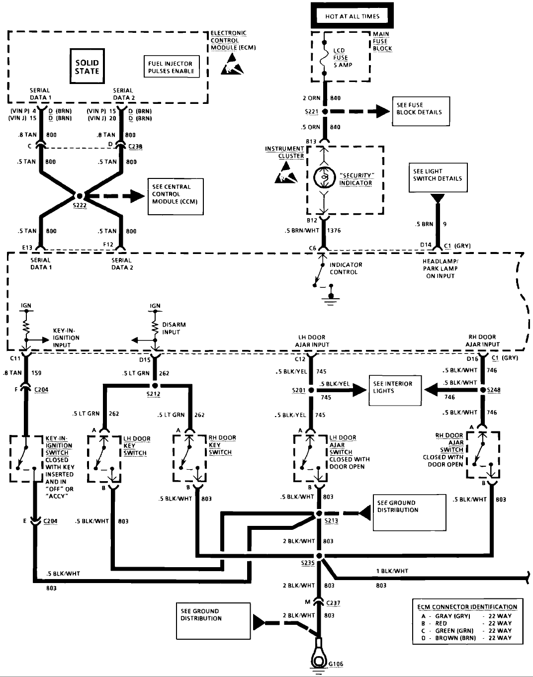
Fig. 3: Sample Diagram: How to Read and Interpret Wiring Diagrams. Click image to see an enlarged view.

Fig. Fig.
4: Wiring Diagram Symbols. Click image .This is a BASIC Installtion Diagram used when Installing the Bypass Module to GM’s VATS/PASSKEY Anti-theft system.
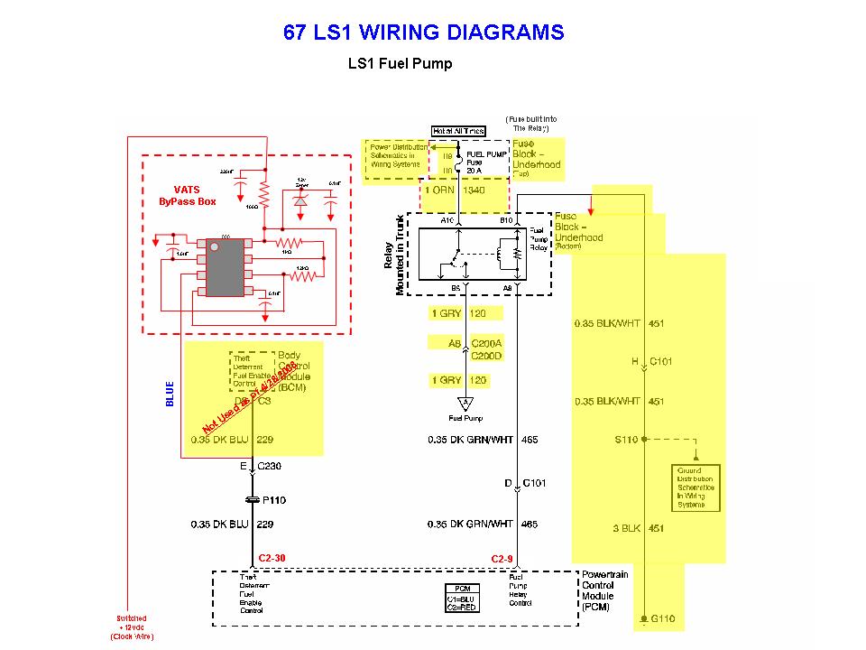
The wires that are needed for this Installation are marked in RED in this diagram, all others to be taped up and do not use. RED RED to 12 Volts Constant fused at 3 Amps ORANGE to VATS wire that tests (-)Negative or Ground.
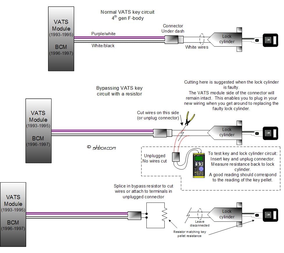
Please study the following information carefully WHEN INSTALLING REMOTE START systems on a or later GM car or truck.. Introduced in , GM has changed the VATS anti theft system to Pass-Lock system. This is a similar device to the VATS system, in that there is .

VATS/PASSKEY Diagram for 8-Pin Harness on IF Bypass Module: This is a DIAGRAM for GM’s VATS/PASSKEY ANTI-THEFT system for the IF BYPASS MODULE. You will ONLY need to use the wires in the schematron.org HARNESS that are marked in ‘RED” for VATS/PASSKEY system, all other wires from the 8-Pin Harness, tape up and Do Not Use!!
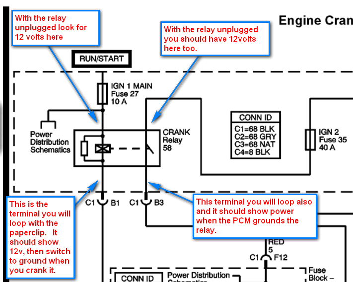
DIP Switch “0. May 23, · I was looking at one of my starting system wiring diagrams and I think I found an easy VATS bypass that wouldnt require a trip to Radio Shack or ecklerscamaro. The wiring from these leaf contacts travels down along the steering column wire harness, where it connects to the vehicle harness at the base of the column.
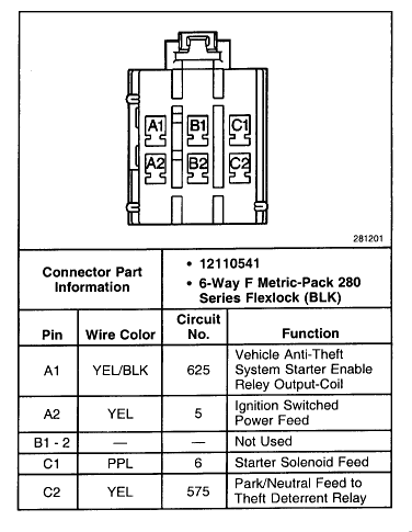
Usually, the VATS wiring in the column is in an orange covered cable, sometimes black, and has a lone two-wire .GM VATS Pellet Inserted ChipVATS and PASSKey Vehicle Anti-Theft Systems – schematron.org