
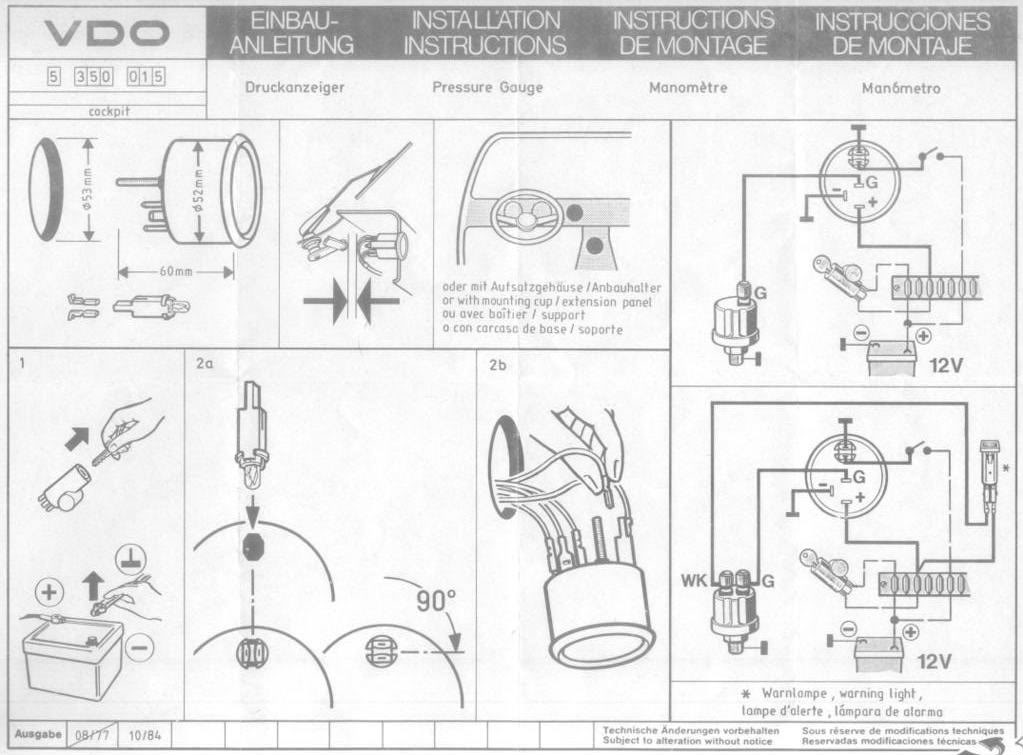
without previous written permission by the Siemens VDO Trading GmbH nor used in contradiction to . (diameter 52 mm: tachometer, clock, operating hours counter, four-stroke), by terminal W of the alternator in the case of diesel engines.
an alternator, you must first wire it (Diagram. E) and calibrate it Diagram E.
Proper wiring of the VDO Programmable Tachometer with typical ignition systems . Diagram B.
VDO Programmable Tachometer Dimensional Drawings VDO Tachometer is not included. This sensor this installation manual are available in three diam- eters: 3 .
rect calibration value for the diesel engine and ignition sys-. The VDO Programmable Tachometers featured in this VDO’s Inductive Sensor is Part # or 02 1.) 2.
installation manual are available in three diameters: ” gasoline engines or with diesel engines, and can be used with 1. f 9W^YdY_^ 3_Y\ 2QddUbi 0 –.
recheck your wiring. you will need to configure it as shown in Diagram D.
When using the VDO Tachometer with Gauge.Programmable Tachometers. View as List Grid.
8, RPM 2 1/16″ Tachometer and Black Mounting Cup, 12V. Add to Wishlist | Add to Compare; Learn More.
Vision Black 8, RPM 2 1/16″ Tachometer, 12V. Find a VDO authorized distributor.
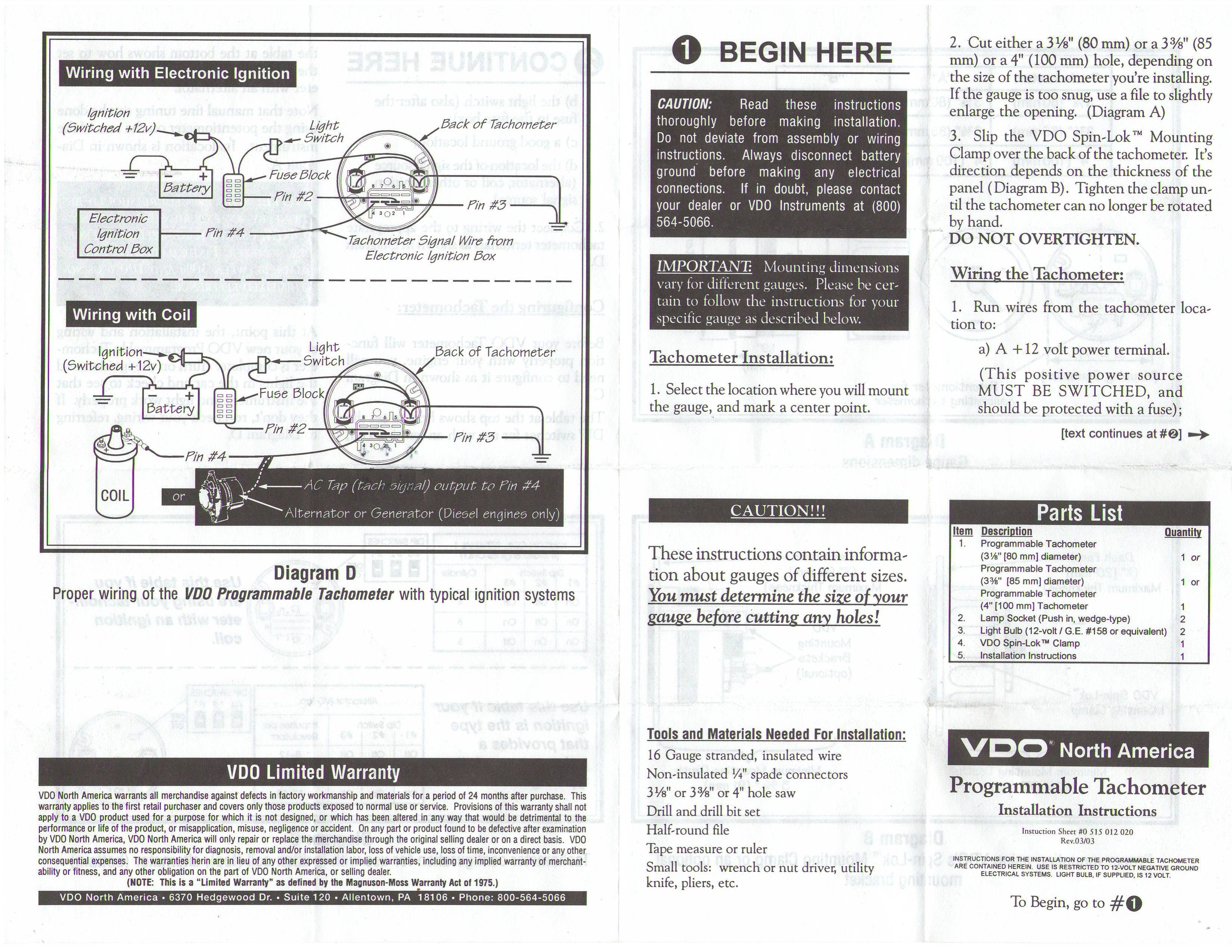
Theory of Operation: After designing and installing the digital tachometer described above, and publishing this project on the world wide web, I had a few readers ask about applying this design to an analog tachometer. Diagram E Proper wiring of the VDO Programmable Tachometer with typical ignition systems ˘ˇˆ ˙˘ ˝ˇ!
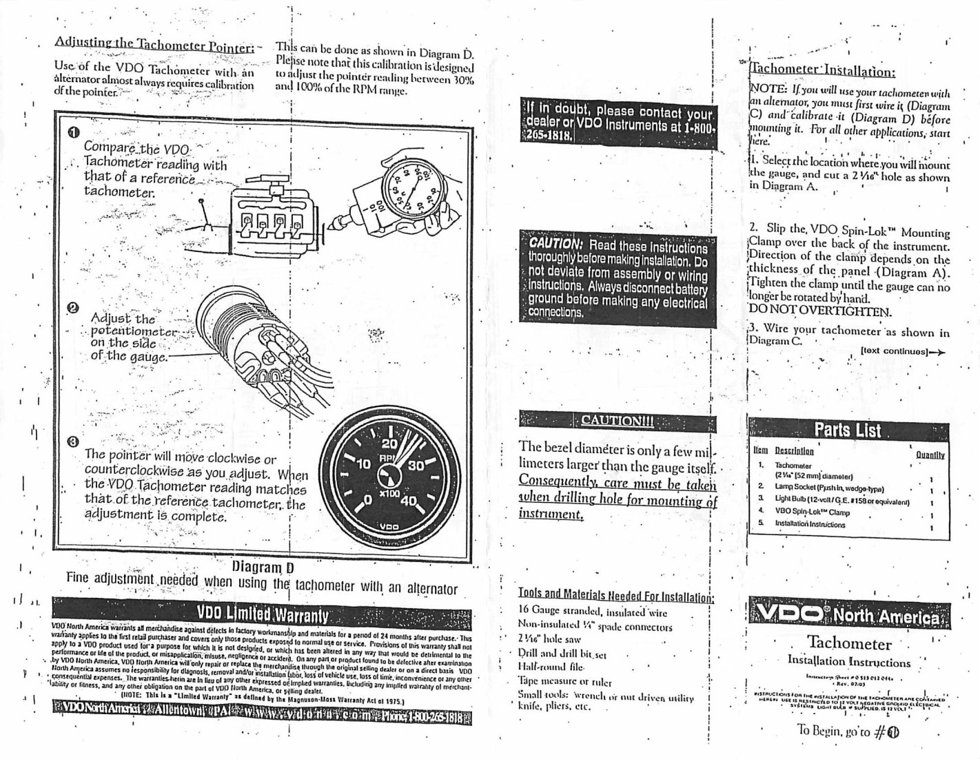
“˙ Diagram F Fine adjustment of the VDO Tachometer when used with an alternator Compare the VDO Tachometer reading with that of a reference tachometer. Adjust the potentiometer on the back of the tach. When the VDO Tachometer reading.
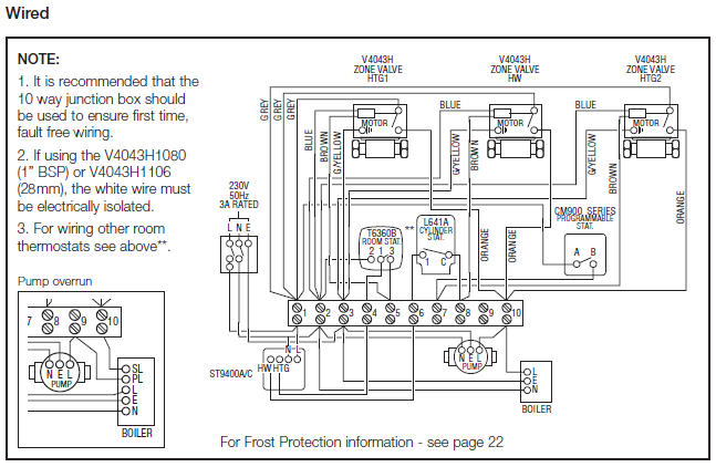
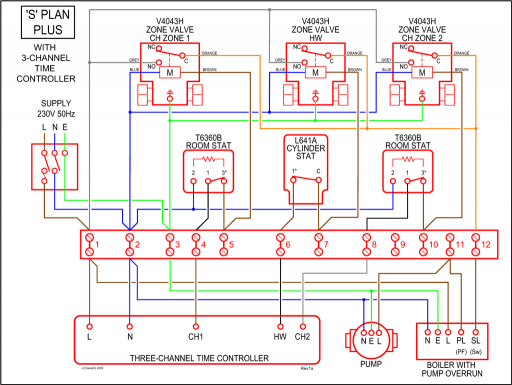
Vdo Diesel Tachometer Wiring Diagram For ducati & rotax vdo vdo instruments and accessories, before your vdo tachometer will function properly with your engine, you will need to configure it as shown in diagram e the table in diagram e shows how to set the dip . VDO Tachometer is not included. This sensor is avail-able from your auto parts dealer.
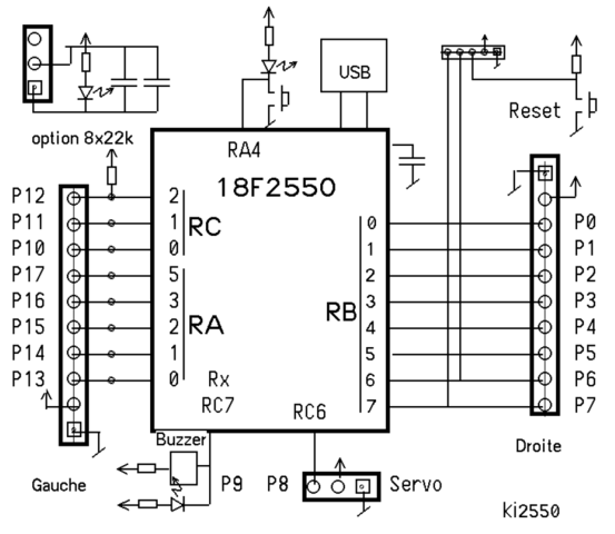
(Part numbers forhe t VDO Generator Sensor is Part # VDO’s Inductive Sensor is Part # ) 1. Refer to Diagram B for dimensions.
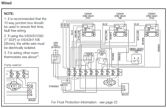
The 3¹⁄₈” (80 mm) tachometer requires a hole diameter of 3¹⁄₈”.Diesel Tachometer Wiring Diagram | Wiring LibraryVW Diesel Tachometer