Vw Beetle Tachometer Installation
VDO cockpit vision VDO cockpit international . (diameter 52 mm: tachometer, clock, operating hours counter, pyrometer; diameter . Wiring diagrams. 2 – 9.
the gauge, and cut a 2¹⁄₁₆” hole as shown in Diagram A. 2. Slip the VDO Spin- Lok™ Mounting.
Ù. [text continues at #Ë].
Tachometer Wiring: 1. Run wires from.
Tachometer, without Display. GB .
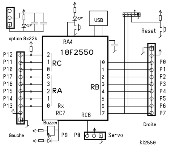
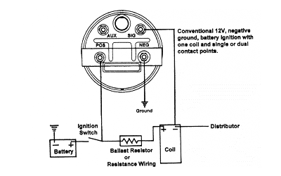
Insulate exposed stranded wires to prevent short circuits. • Caution: Risk of according to the electrical wiring diagram. Refer to Diagram B for dimensions.
TACHOMETER INSTALLATION
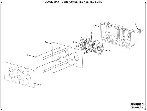
shown in Diagram C. You may also mount the tachometer the installation, wiring, calibration and operation of all.

VDO. VDO Programmable Tachometer Dimensional Drawings. 3¹⁄₈” (80 Refer to Diagram B for dimensions.
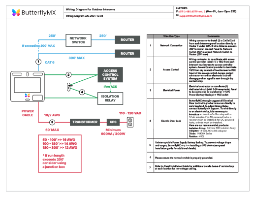
the installation, wiring, calibration and operation of all.VDO Wiring Diagrams – Diagram will open in a new window. Fuel.
How to install a tachometer in your classic car or truck.
Voltmeter. Oil Pressure – no light.
Oil Pressure – w/ warning light. Oil Temperature – no light. Oil Temperature – w/ warning light.
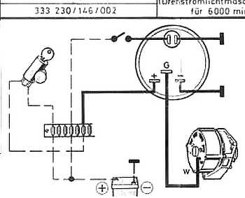
Electric Tachometer or Speedometer w/o Odometer. Electric Speedometer or Tachometer w/ Odometer/Rev Counter.
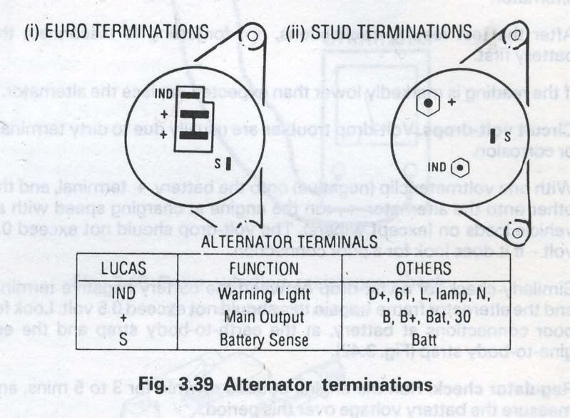
Alternator Driven Tachometer. Cylinder.
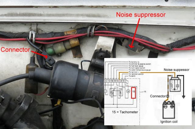
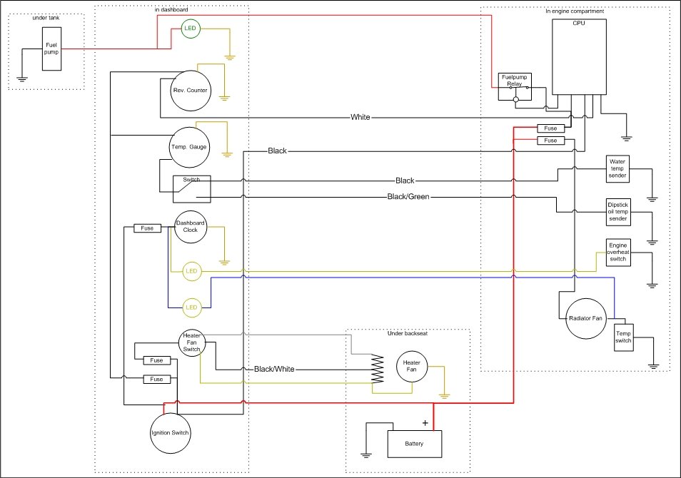
The red wire is for the ignition switch. Connect this red wire so that when the car is started the tachometer will begin operating.
T-splice wire adapters allow for new wires to be spliced together with existing ones using pressure connectors that you squeeze around the existing wire . Comments: my lcd on rev counter as just vanished it,s a could you give me any clue,s many thank,s stu February 11, Followup from the Pelican Staff: I think VDOrepair fixes this issue.
Technical Product Manual VDO cockpit vision VDO cockpit international Contents Page General informations 2 – 2 Technical data 2 – 4 Speed sensor 2 – 8 Wiring diagrams 2 – 9 Setting 2 – 11 Operation 2 – 16 Speed display 2 – 17 Testing instructions 2 – 18 Instruments survey 2 – 21 Installation instructions. VDO has tried to answer most of your questions regarding Installation and Trouble shooting of VDO Performance Instruments.
You need to have Acrobat reader to open these instruction sheets.Yanmar rev counter stopped showing revs; sensor or tacho problem?Wiring in VDO Rev Counter | LandyZone – Land Rover Forum