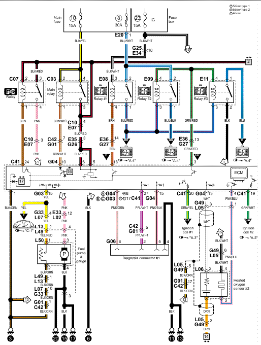
TRUCK SERVICE MANUAL TM &P-1 INSTRUMENTS Fig.
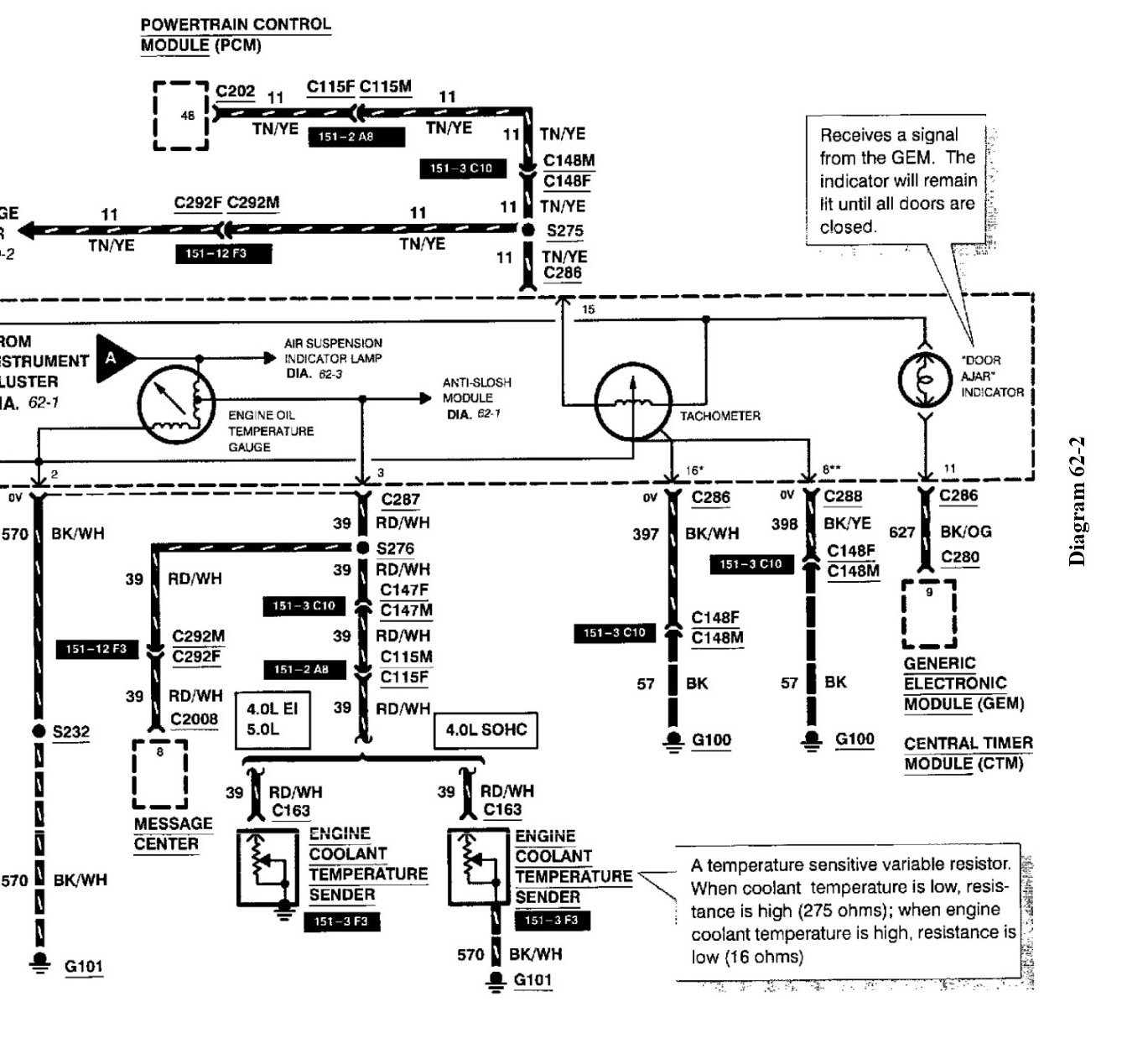
20 Water Temperature Gauge Circuit Diagram temperature coefficient. The decrease.
80mm & mm Electronic Tachometer – Wiring Diagram & Calibration Switch Table 52mm Water & Oil Temperature, Oil Pressure, Fuel Gauge, Voltmeter and. 80mm & mm Electronic Tachometer – Wiring Diagram & Calibration Switch Table 52mm Water & Oil Temperature, Oil Pressure, Fuel Gauge, Voltmeter and.

This temperature gauge kit is designed to fit an engine which uses a water hose with an inside diameter of ¾”, for example, In addition to the wiring instructions provided by Auto Meter, it is also necessary to ground the Wiring Diagrams. Installing a tachometer or water temp gauge is a fairly easy task.
The red wire is linked to a key-switched ignition source, to transfer power to the tachometer.WIRING DIAGRAMS – 4D-1 Wiring Colors for MerCruiser BIA Color Code Where Used Black All Grounds Brown Reference Electrode-MerCathode Orange Anode Electrode-MerCathode Lt. Blue/White Trim- ”Up” Switch Gray Tachometer Signal Green/White Trim -”Down” Switch Tan Water Temperature Sender to Gauge Lt.
Blue Oil Pressure Sender. Wiring In Water Temp Gauge – posted in Problems, Questions and Technical: Hi all, I have tried to wire in a water temperature gauge in, the TIM electrical one, and am having no joy. And i have tried searching TMF and MiniFinity forums but cant find any solutions!
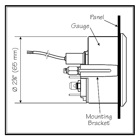
4. Connect a wire to the gauge stud marked “I” (ignition) and secure with nut and lock washer. Connect opposite end to a 12VDC circuit that is activated by the ignition switch.

5. Connect a wire to the gauge stud marked “GND” Connect opposite end to the boat’s electrical ground. Replacement 14 Pole Harness with mm Leads for 1 Viewline Speedometer or Tachometer with 5 Telltales.
Gauge Set Installation Manuals. General Installation Manual Download 2″ Full Sweep Coolant and Trans Temp Gauge Installation Guide. Download SN81SF Sky Fence Wiring Diagram.
SN84 6 Gauge Wire Harness. Download SN84 Installation Guide. Fuel Sender with Float Arm.Fig. 20 Water Temperature Gauge Circuit DiagramWiring In Water Temp Gauge – Problems, Questions and Technical – The Mini Forum
