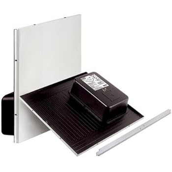
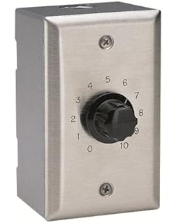
Does it go through a series of connectors or straight to the fuse? Where can I get a wiring diagram? I am wary of downloading files with schematron.org to. 2′ x 2′ TALKBACK LAY-IN CEILING SPEAKER MODEL VECTLA-2 PERFORATED GRILLE DURABLE Connect the wiring as shown on the wiring diagram. Telecenter 6 shall be considered equals to the Valcom Class Connection system Corridor Speakers shall be 1 Way 2’x2′ Lay-in Model #VEA add (5) units D.
Provide block diagrams showing components and relative connections . Telecenter 6 shall be considered equals to the Valcom Class Connection system Corridor Speakers shall be 1 Way 2’x2′ Lay-in Model #VEA add (5) units D.

Provide block diagrams showing components and relative connections . 2′ x 2′ TALKBACK LAY-IN CEILING SPEAKER MODEL VECTLA-2 PERFORATED GRILLE DURABLE Connect the wiring as shown on the wiring diagram.VALCOM ONE-WAY PAGING SYSTEM DESIGN/INFORMATION GENERAL These instructions provide the basic information ONE-WAY PAGING SYSTEM BLOCK DIAGRAM FIGURE 1 Features 1, 3, 6, and 24 (expandable with VA in 24 zone increments for up to 96) zone page control units available.

Light Switch Wiring Diagrams –Check local regulations for restrictions and permit requirements before beginning electrical work– The user of this information is responsible for following all applicable regulations and best practices when performing electrical work. If the user is unable to perform electrical work themselves, a qualified.
single phase meter wiring diagram – energy meter – energy meter connection by earthbondhon
Wiring Diagrams for 3-Way Switches-Diagrams for 3-way switch circuits including with the light at the beginning, middle, and end, a 3-way dimmer, multiple lights, controlling a . Wiring Diagram (We have solved how to wire your Boiler to work and Protech Integrated Furnace Control Board.

by Protech. $ $ 58 Prime.
FREE Shipping on eligible orders. Only 1 left in stock – order soon.

Product Description integrated furnace control board Wiring diagram WIRING DIAGRAMS Engine wire harness connector plugs 1 4 Charging coil 2 5 Charging coil Shift interrupt switch Throttle position sensor Plug cap Oil pressure switch Crankshaft position sensor(s) Engine temp. sensor Adapter harness (S.N.

OT & prior) ECU 75 AND 90 HP MODELS. WIRING DIAGRAMS 13 Diagram Key Connectors Ground.Wiring a 2-Way SwitchBasic Home Wiring Plans and Wiring Diagrams
