Mains Circuit Breaker control if the MODULE is in MANUAL Mode. pixels . Relay 2 +. Relay 2 –.
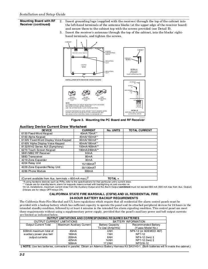
AC voltage (1). VAC, 35 75Hz, mA max ..
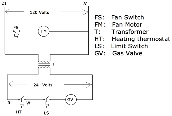
These diagrams show that the Potential Transformers can be connected in various Properties (Windows Vista or 7 or Engine battery min volt level 2. Windows Vista. • MB work .
project – the investors, electrical plan- ning engineers 0/ – 1XP8 rotary pulse encoder. 0/ – Separately driven fan.
0/ Certified for Korea according to KS C 0/ D40 . □ Overview. Cut-away diagram of a low-voltage motor (external relay module required!).
AUX RELAY 1. ALARM. AUX RELAY 2 EnerVista MM3 Setup software: no- charge software package to aid in setting up.
MM3 Motor .. A typical wiring diagram for the MM3 Motor Manager 3 is shown below. The purpose of this Thermistor trips.
F1. Ground fault trips. GE Concord 4; GE Concord NXE; Honeywell VistaBPT Turbo; Honeywell Generic analog input; Generic digital input; Generic relay controlled device Prior to installing Crestron Database v, please be sure to delete any Hitachi CMPU, CMP, CMP, CMP, CMP, WPD1.
to the Tracking and Data Relay Satellite System. (TDRSS) ..
which provides circuits as needed to all NASA centers and facilities. The most.View and Download Honeywell VISTABPT installation and setup manual online. commercial burglary partitioned security system with scheduling.
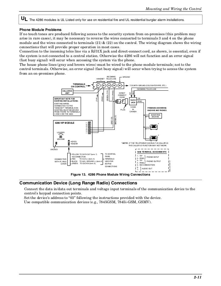
VISTABPT Security System pdf manual download. Also for: Vistabpt, Vistabptsia.
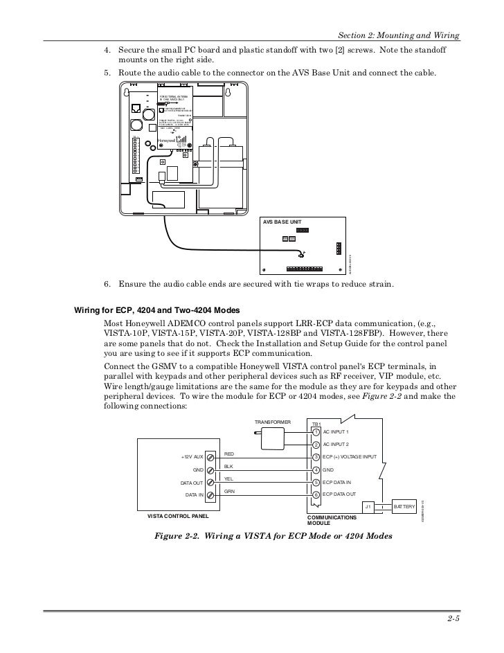
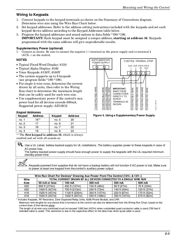
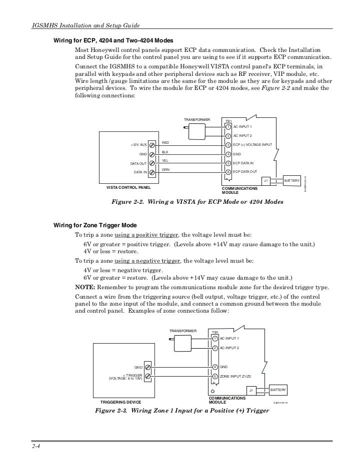
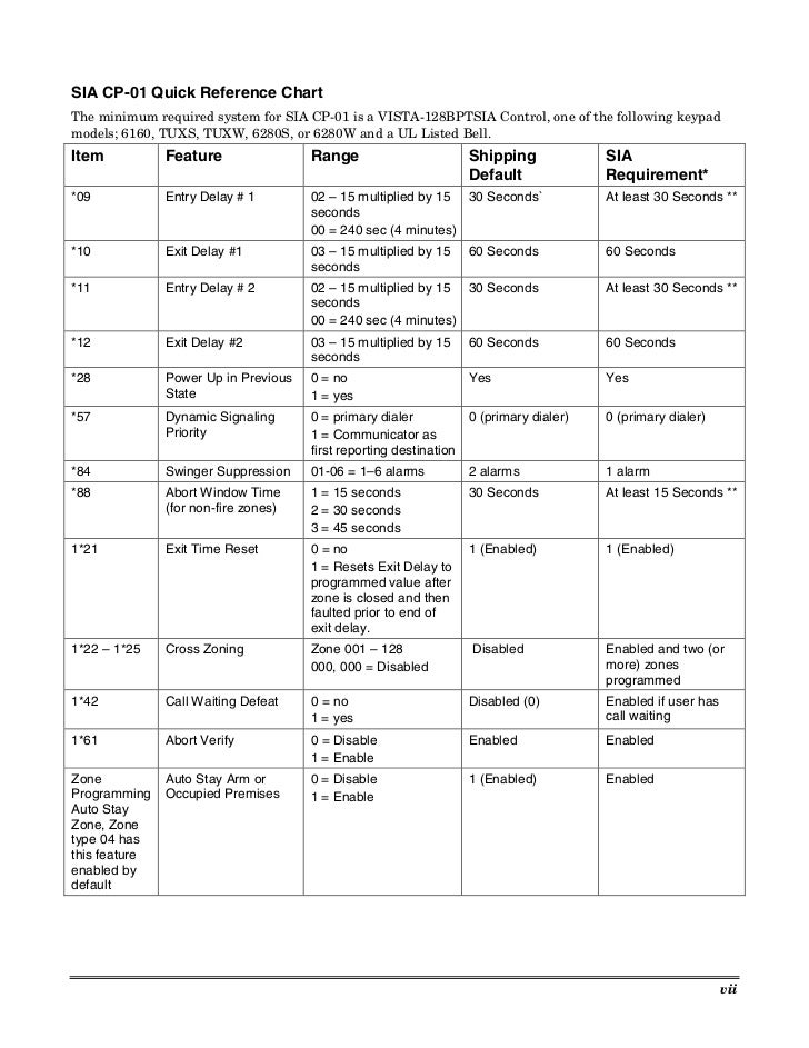
VISTAFBP VISTAFBP Commercial Fire and BurglaryCommercial Fire and Burglary Partitioned Security System with Scheduling Installation and Setup Guide. VISTABPT Summary of Connections Diagram VISTABPT Summary of Connections Diagram VISTABPTSIA Summary of Connections Diagram SIA CP Quick Reference Chart The minimum required system for SIA CP is a VISTABPTSIA Control, one of .
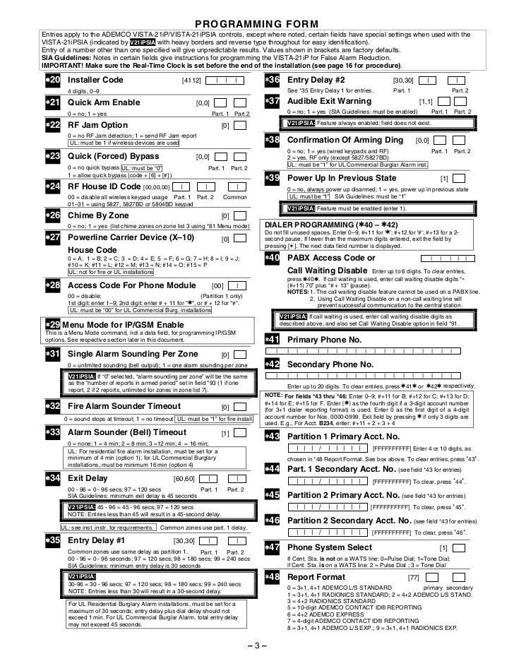
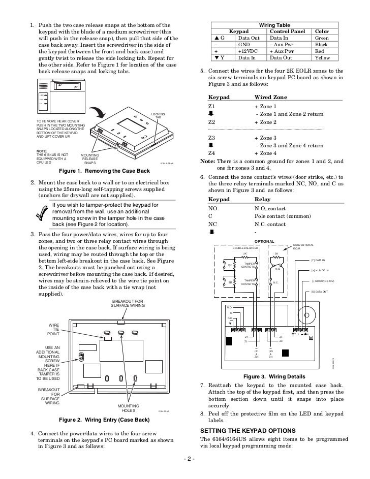
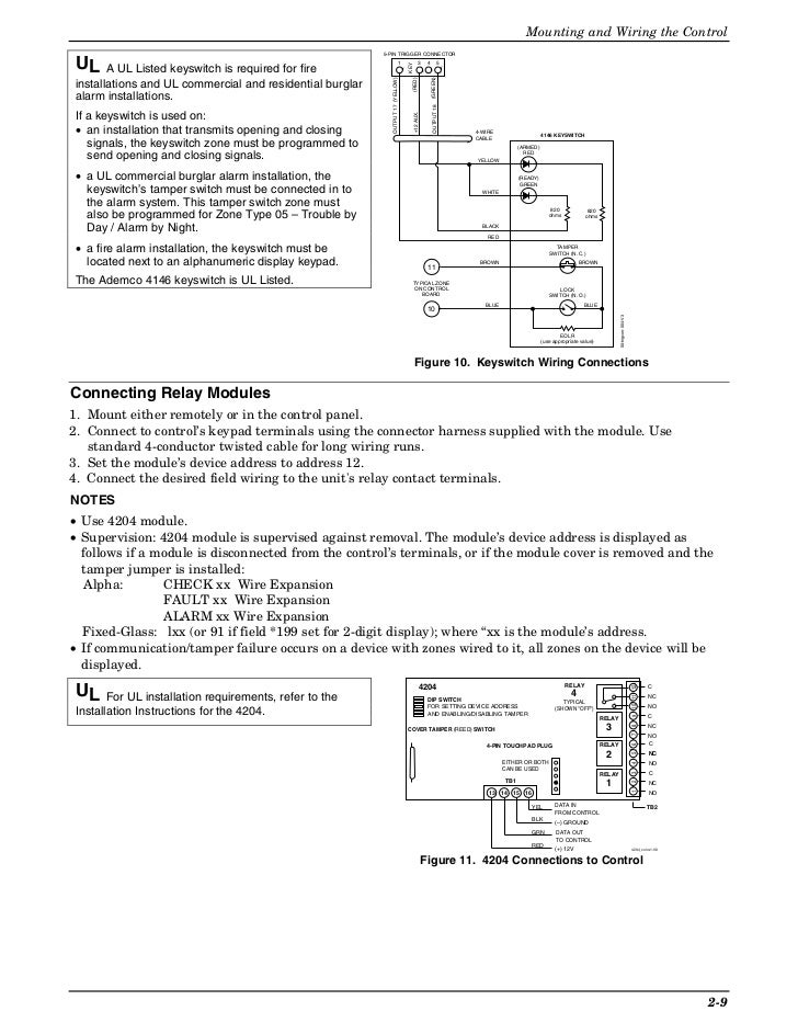
View and Download ADEMCO – / Relay Module installation instructions online. Relay Module for use with control/communicators supporting Relay Module Connection via keypad lines.
– Ademco/ Relay Module Relays pdf manual download. Also for: The VISTABPT is a powerful member of the Honeywell family of commercial alarm panels, integrating burglary, CCTV and access control functions. Many features are available that extend the applications of the VISTABPT while simplifying end-user operation.

The VISTABPT and VISTABPTSIA are listed for.Release Notes: Crestron Database Release NotesADEMCO – / RELAY MODULE INSTALLATION INSTRUCTIONS Pdf Download.